
Common-rail fuel oil injection system injector failure diagnosing method

A fuel injection system and fault diagnosis technology, which is applied to fuel injection devices, charging systems, instruments, etc., can solve the problems of not being able to apply the common rail fuel injection system and increase costs, and achieve easy implementation, low cost, and reliable judgment Effect

Active Publication Date: 2006-05-17
CHINA FIRST AUTOMOBILE
View PDF1 Cites 42 Cited by
  • Summary
  • Abstract
  • Description
  • Claims
  • Application Information

AI Technical Summary

Problems solved by technology

The method of installing a speed sensor with a higher pulse frequency on the camshaft of the fuel injection pump is adopted, and the relationship between the transient speed fluctuation and the pressure change of the plunger chamber is used to judge the failure of the fuel injection system. This method is only suitable for electronically controlled diesel engine pumps—— pipe-nozzle fuel injection system, but not common rail fuel injection system; another method is to use pressure sensors or collect vibration and noise signals of the engine for fault judgment, but these methods need to add additional sensors on the one hand, and on the other hand On the one hand, rich experience is needed to carefully screen and analyze the measurement signals. Therefore, the actual application not only increases the cost, but also easily leads to misjudgment

Method used


Image

  • Common-rail fuel oil injection system injector failure diagnosing method
  • Common-rail fuel oil injection system injector failure diagnosing method
  • Common-rail fuel oil injection system injector failure diagnosing method

Examples


Embodiment Construction

[0016] The specific implementation, working principle and preferred embodiment of the fuel injector fault diagnosis method of the present invention will be described in detail below in conjunction with the accompanying drawings.

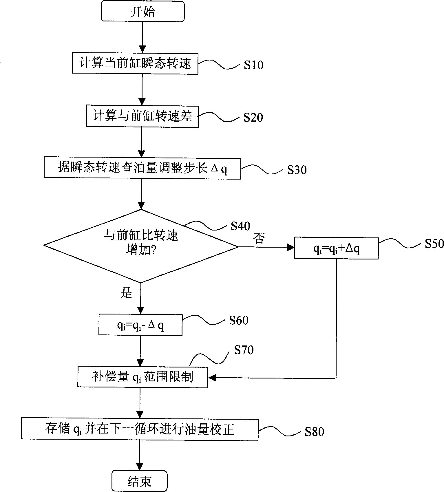
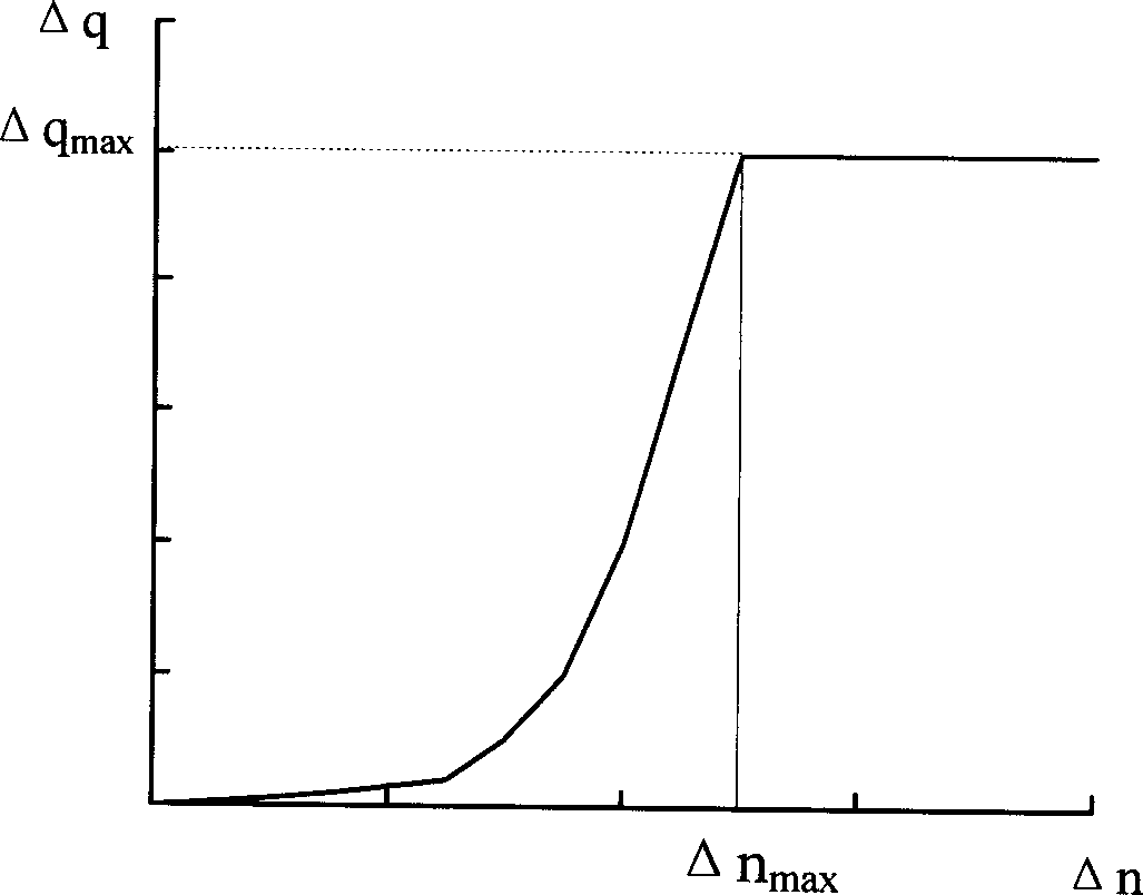
[0017] The accompanying drawing takes a six-cylinder four-stroke common rail diesel engine as an example, and the ignition sequence of the engine is 1-5-3-6-2-4. The crankshaft (or flywheel) chainring used to measure the instantaneous speed of the engine has a structure of 48 missing 3 teeth. The pulse signal tooth plate installed on the high-pressure oil supply pump to identify the cylinder has a 6+1 tooth structure. figure 1 Indicates the phase relationship between the engine crankshaft and the high-pressure fuel pump speed pulse signal. exist figure 1 Among them, the compression top dead center of the corresponding cylinder is located at about 75° crankshaft angle after the cylinder signal is judged. In order to make the collected signal reflec...


PUM


Abstract

The present invention relates to a diagnostic method of injector failure in common rail fuel injection system. Said method includes the following steps: firstly, utilizing acquisition and analysis of transient rotational speed of engine, then utilizing the injection compensation quantity obtained according to engine inter-cylinder balanced algorithm to make statistical analysis of compensation quantity variable tendency and adopting probability statistic method to judge the failure of injection system, so that it can greatly raise the accuracy of failure judgment of fuel injection system.

Description

technical field [0001] The invention relates to a fault diagnosis method of a diesel engine fuel injection system, in particular to a fuel injector fault diagnosis method of a common rail fuel injection system. Background technique [0002] Many of the existing electronically controlled diesel injection systems already have fuel injection system fault diagnosis devices. Chinese patent CN1112508 discloses a method and device for fault diagnosis of a diesel engine injection system. The method of installing a speed sensor with a higher pulse frequency on the camshaft of the fuel injection pump is adopted, and the relationship between the transient speed fluctuation and the pressure change of the plunger chamber is used to judge the failure of the fuel injection system. This method is only suitable for electronically controlled diesel engine pumps—— pipe-nozzle fuel injection system, but not common rail fuel injection system; another method is to use pressure sensors or collect...

Claims


Application Information

Patent Timeline
IPC IPC(8): F02M65/00
Inventor 宋国民季晓华陆召振张爱云徐剑飞
Owner CHINA FIRST AUTOMOBILE
Learn More