Supercharge Your Innovation With Domain-Expert AI Agents!

Consequent water inlet valve

A water inlet valve, forward technology, applied in the direction of valve lift, valve details, valve device, etc., can solve the problems of valve top opening, lower reliability, soft material wear, etc., to overcome friction damage, simple structure, and close reliable effect

Inactive Publication Date: 2006-05-17
崔文莉
View PDF0 Cites 0 Cited by
  • Summary
  • Abstract
  • Description
  • Claims
  • Application Information

AI Technical Summary

Problems solved by technology

This design has three defects: first, when the water surge pressure is high, it is easy to push the valve open, resulting in water leakage; second, because the top of the water outlet is made of hard material, the material used to block the water outlet is soft After a long period of friction, the soft material wears away, which also leads to water leakage; third, the use of leverage makes the structure complex and reduces its reliability. Once a failure occurs, it will also cause water leakage.

Method used


Image

  • Consequent water inlet valve

Examples


Embodiment Construction

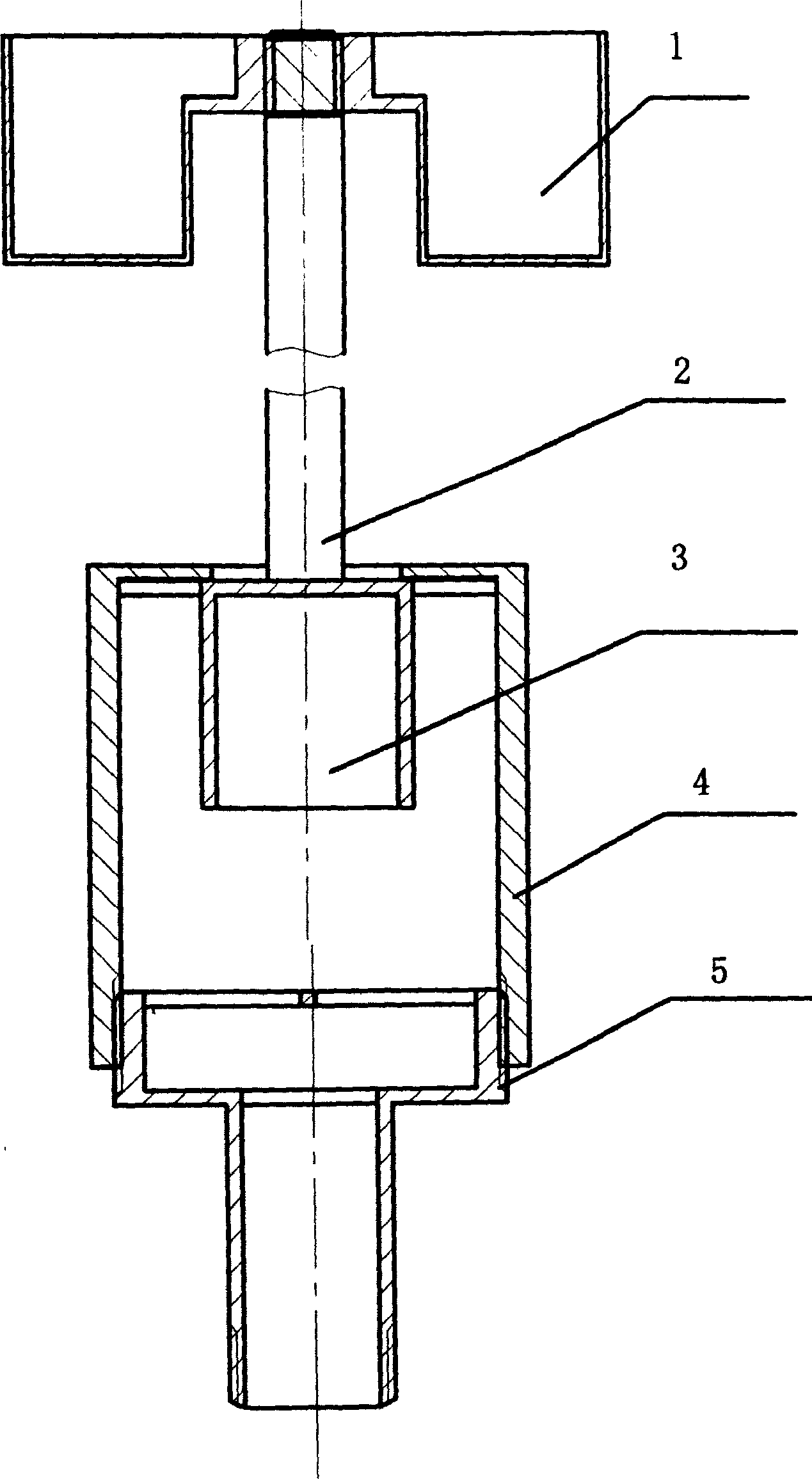
[0009] The upper and lower valve sleeves, counterweight container and valve core can be made by plastic injection molding, metal stamping, ceramic sintering and other methods. If the cross frame at the top of the lower valve sleeve is made of plastic and metal materials, it can be welded; if ceramic materials are used, the two blanks are first prepared, then the cross is bonded, and finally fired. Fill the valve core with buoyant material or make a closed space under the valve plate. After the valve core is put into the upper valve sleeve, the two valve sleeves are screwed together, and the top of the valve stem is then screwed into the counterweight container.


PUM


Abstract

The present invention relates to a forward water-feeding valve which can be used for regulating water quantity and is applicable to water tank of toilet and solar and electric water-heater water storage container. Said water-feeding valve includes the following several portions: valve cavity, valve core, valve rod and counterweight container. Said invention also provides the concrete structure of the above-mentioned every portion.

Description

Technical field: [0001] The forward water inlet valve of the present invention belongs to the water supply hardware. technical background: [0002] For the water storage containers involved in daily sanitary ware, solar water heaters and electric water heaters, the water inlet valves all use lever force to close against the direction of water gushing and to open along the direction of water gushing. This design has three defects: first, when the water surge pressure is high, it is easy to push the valve open, resulting in water leakage; second, because the top of the water outlet is made of hard material, the material used to block the water outlet is soft For soft materials, after a long period of friction, soft materials are worn out, which also leads to water leakage; third, the use of leverage makes the structure complex and reduces its reliability, and once a failure occurs, it will also cause water leakage. Invention content: [0003] The purpose of the present inve...

Claims


Application Information

Patent Timeline
Patent Type & Authority Applications(China)
IPC IPC(8): F16K1/00F16K31/22
Inventor 李善锐崔文莉
Owner 崔文莉
Features
  • R&D
  • Intellectual Property
  • Life Sciences
  • Materials
  • Tech Scout
  • Unparalleled Data Quality
  • Higher Quality Content
  • 60% Fewer Hallucinations
Learn More