
Solar energy thermoelectric co-supply system

A technology of combined heat and power and solar energy, applied in solar heating systems, solar thermal power generation, solar thermal energy, etc., can solve the problems of untargeted use of sunlight spectrum energy, limited space for increasing concentration ratio, and high cost of lens concentrators , to achieve the effects of improving solar energy utilization efficiency, improving photoelectric conversion efficiency, and improving tracking accuracy

Inactive Publication Date: 2006-05-17
INST OF ELECTRICAL ENG CHINESE ACAD OF SCI
View PDF1 Cites 66 Cited by
  • Summary
  • Abstract
  • Description
  • Claims
  • Application Information

AI Technical Summary

Problems solved by technology

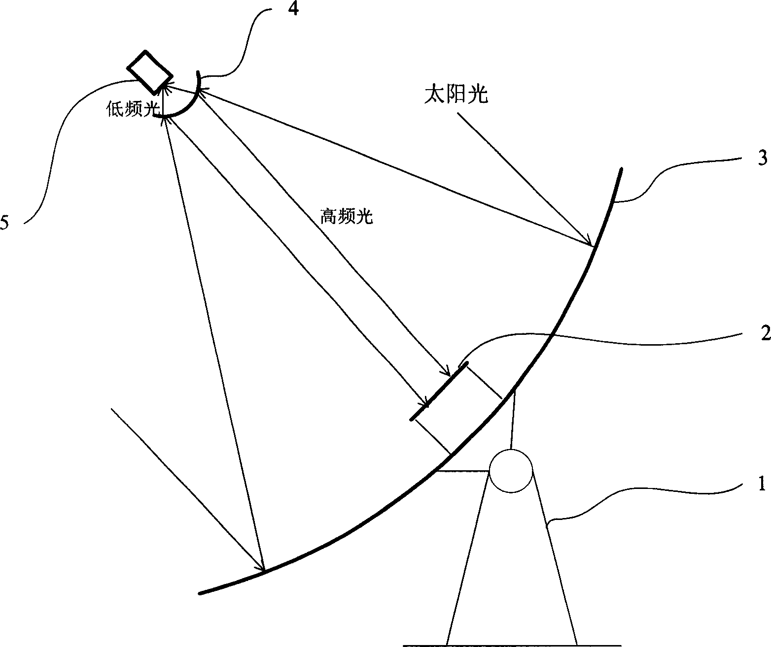
[0003] In order to overcome the above-mentioned disadvantages of high cost of the lens concentrator, limited improvement space of the concentrating ratio, untargeted use of sunlight spectrum energy, and insufficient utilization of solar energy, the present invention proposes a rotating parabolic concentrator as a primary concentrator, Concentrating direct sunlight with high concentration ratio photovoltaic cells, rotating hyperboloid spectrum control system as a secondary reflection and spectrum splitting system, splitting the spectrum for power generation and heat supply respectively, adopting active cooling method for solar cogeneration system of concentrating photovoltaic cells

Method used


Image

  • Solar energy thermoelectric co-supply system
  • Solar energy thermoelectric co-supply system
  • Solar energy thermoelectric co-supply system

Examples


Embodiment Construction

[0017] The present invention will be further described below in conjunction with the accompanying drawings and specific embodiments.

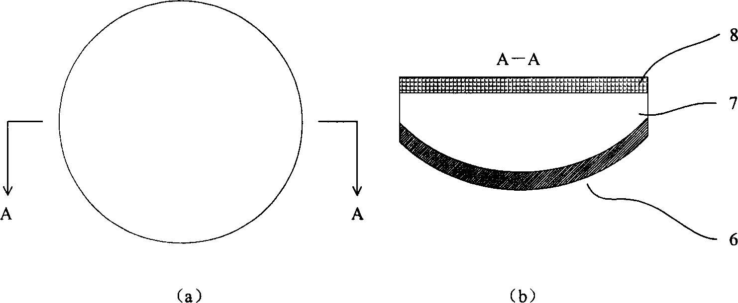
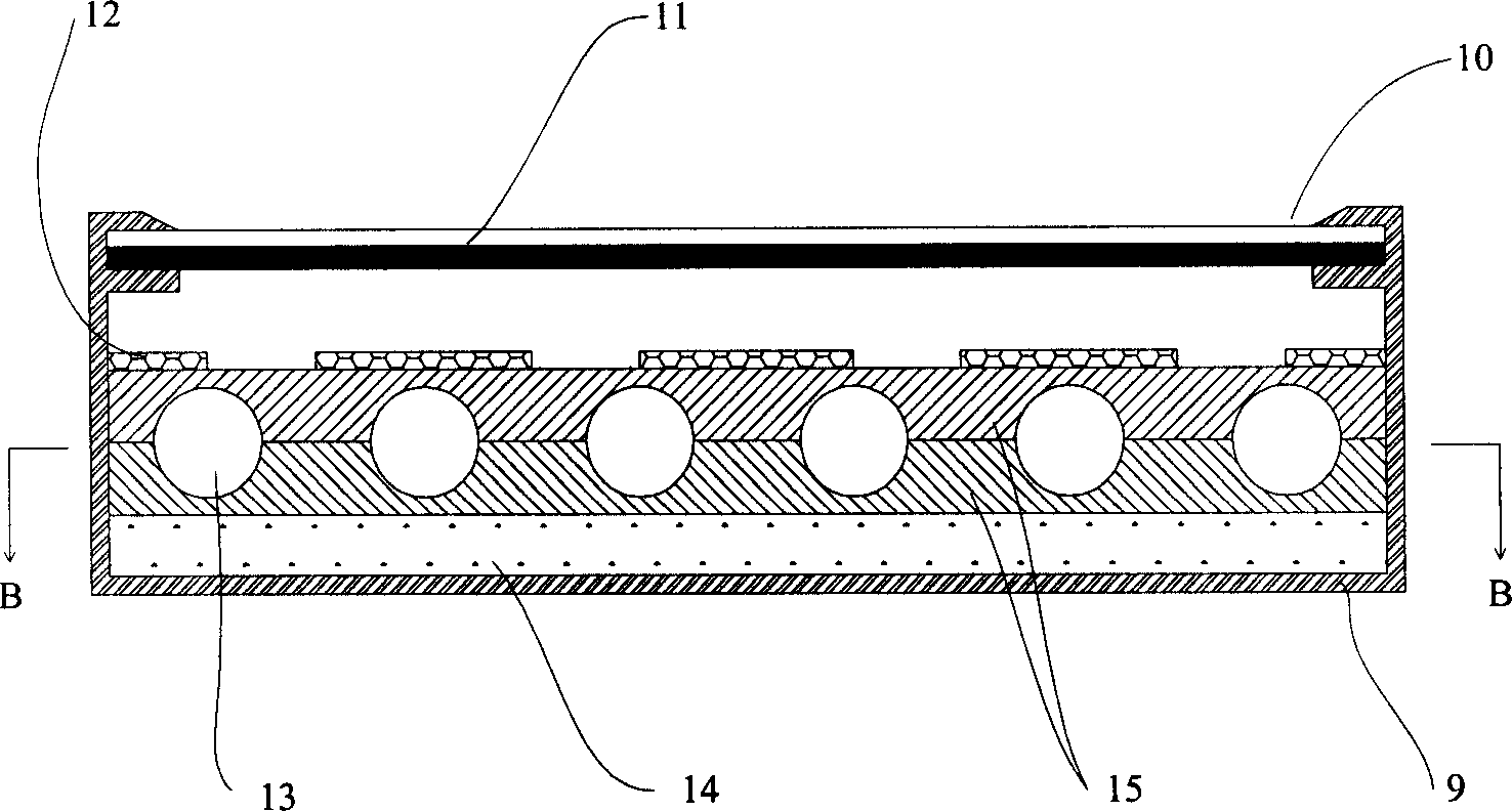
[0018] figure 1 System diagram of the solar cogeneration system shown. The present invention is mainly composed of a supporting frame, a rotating parabolic concentrator 3, a concentrating photovoltaic cell group 2, a rotating hyperboloid spectrum control system 4 and a heat pipe water heater 5. The rotating parabolic condenser 3 is installed on the support frame 1, the focal axis of the rotating hyperboloid spectrum division control system 4 coincides with the focal axis of the rotating parabolic condenser 3, and is installed before the focus of the rotating parabolic condenser 3, and the focus of the rotating parabolic condenser 3 and the rotation The place where the left focus of the hyperbolic spectral control system 4 coincides. The convex surface of the rotating hyperboloid spectrum control system 4 faces the concave surface of the rotat...


PUM


Abstract

The present invention relates to a solar heating and power generation combined supply system. Said system includes the following several components: rotating parabolic saucer condenser, rotating hyperbolic spectral control system, light-gathering photovoltaic group battery and hot-pipe type water heater. Said invention also provides the concrete structure of the above-mentioned every portion and the working principle of said system.

Description

technical field [0001] The invention relates to a heat and power cogeneration system, in particular to a cogeneration system utilizing solar power and heat. Background technique [0002] At present, the known solar photovoltaic power generation uses flat-plate photovoltaic cells, which have the disadvantages of low light density and limited use of the solar spectrum, resulting in low efficiency of the entire system. At the same time, the high price of photovoltaic cells also restricts the large-scale promotion and use of flat-panel photovoltaic power stations. In Chinese patent 98117671.2, it is disclosed that a lens is used to achieve a high concentration ratio of sunlight to reduce the use area of ​​photovoltaic cells, and cooling water cools the photovoltaic cells to provide hot water, thereby improving the efficiency of photovoltaic power generation and realizing combined heat and power. But this method still projects all sunlight onto the photovoltaic cell, making phot...

Claims


Application Information

Patent Timeline
Patent Type & Authority Applications(China)
IPC IPC(8): F24S23/71F24S50/20H01L31/052
CPCY02E10/44Y02P80/15F24S10/755F24S23/79F24S20/20
Inventor 李鑫李安定郑飞李斌臧春城
Owner INST OF ELECTRICAL ENG CHINESE ACAD OF SCI
Learn More