Single sweep measurement of multiple optical characteristics

An optical characteristic, optical technology, used in the testing of optical instruments, measuring devices, testing of machine/structural components, etc.

Inactive Publication Date: 2006-05-17
索尔实验室公司
View PDF0 Cites 2 Cited by
  • Summary
  • Abstract
  • Description
  • Claims
  • Application Information

AI Technical Summary

Problems solved by technology

The second method, although only stepping through one wavelength, must stop at each wavelength to measure three different polarization states.

Method used


Image

  • Single sweep measurement of multiple optical characteristics
  • Single sweep measurement of multiple optical characteristics
  • Single sweep measurement of multiple optical characteristics

Examples


Embodiment Construction

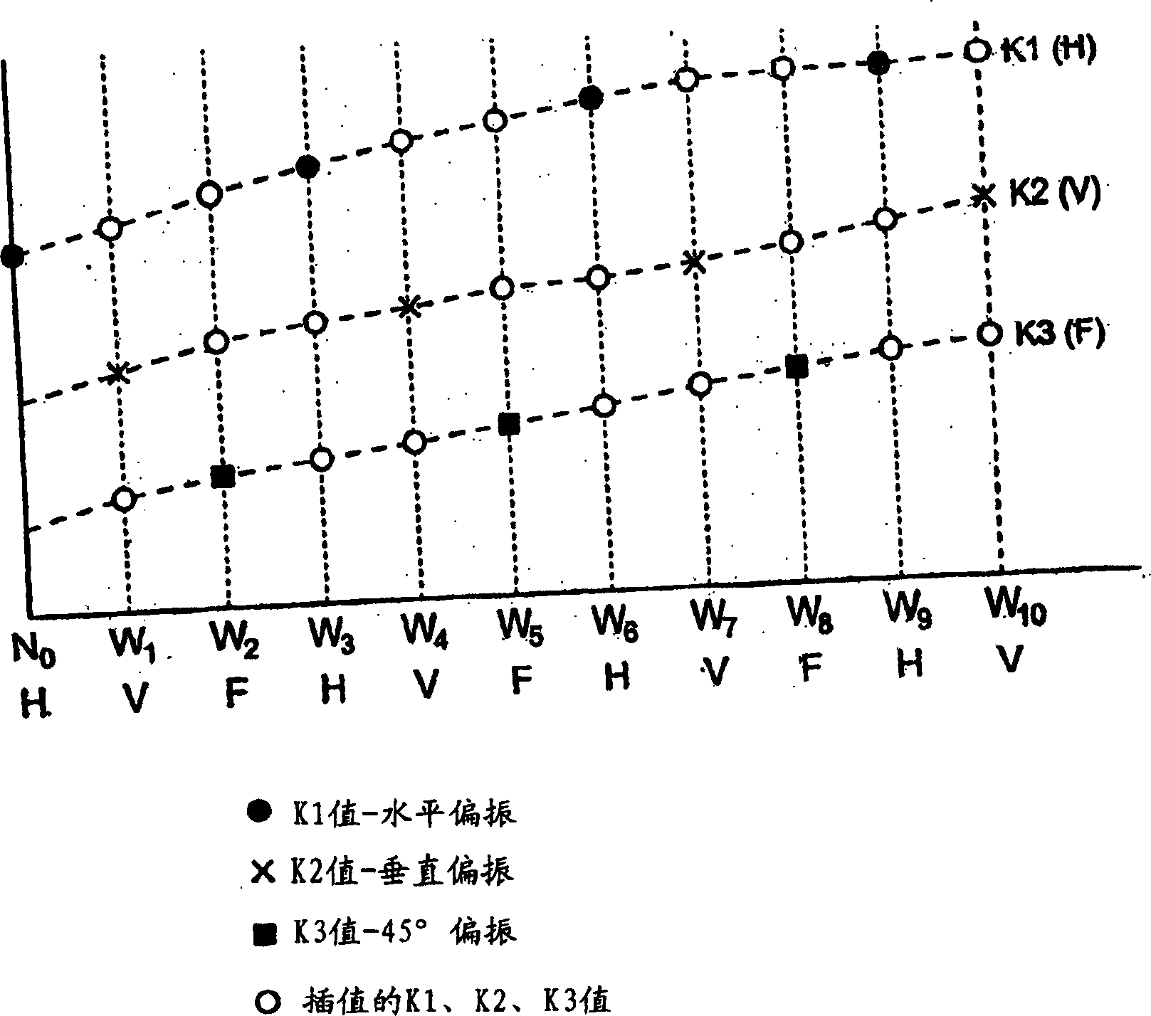
[0021] J i is in the scanning wavelength range ω 0 …ω n The ith Jones vector measured at the ith optical frequency within . Using linear interpolation, the equation for computing the components of the Jones matrix at each optical frequency is:

[0022] K1 k+i =X i / Y i +[(ω i+k -ω i ) / (ω i+3 -ω i )]*[X i+3 / Y i+3 -X i / Y i ]

[0023] K2 k+i =X i+1 / Y i+1 +[(ω i+k -ω i+1 ) / (ω i+4 -ω i+1 )]*[X i+4 / Y i+4 -X i+1 / Y i+1 ]

[0024] K3 k+i =X i+2 / Y i+2 +[(ω i+k -ω i+2 ) / (ω i+5 -ω i+2 )]*[X i+5 / Y i+5 -X i+2 / Y i+2 ]

[0025] K4 k+i =(K3 k+i -K2 k+i ) / (K1 k+i -K3 k+i )

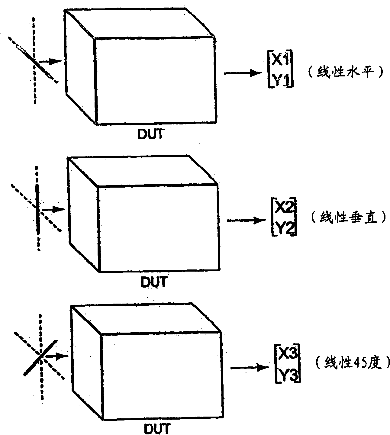
[0026] The calculation starts with i=0 and k=0,1,2. For the three input polarization states, k=0 is equal to the Jones matrix component of the Jones vector measured for the ith optical frequency at the particular input polarization state, k=1 and 2 are provided at the i+1 and i+2th optical frequencies The Jones matrix components at frequency interpolated for the sa...


PUM


Abstract

A method of measuring a plurality of optical properties of an optical device during a single scan of a swept wavelength optical system that cycles an input polarization state at successive optical frequency increments of an optical signal within the wavelength range of the swept wavelength optical system. A wavelength-dependent Jones matrix is ​​calculated from the measured output polarization states, and a number of optical properties are determined from the Jones matrix, the properties including PDL and DGD.

Description

Background of the Invention [0001] The present invention relates to the measurement of optical properties of an optical device to be measured, and more particularly to a method and apparatus for measuring multiple optical properties within a single scan of a scanning wavelength system using Jones matrix characterization. [0002] It is well known in the art that the Jones matrix of any two-port optical device can be measured by utilizing the three known input polarization states and measuring the resulting output polarization state. Polarized light is represented by a two-element complex vector (ie, the Jones vector), two elements of which specify the magnitude and phase of the x and y components of the electric field at a particular point in space. The input and output Jones vectors of the Jones matrix of the optics are related to each other. The Jones matrix representation is established by measuring the three output Jones vectors in response to three known input excitation...

Claims


Application Information

Patent Timeline
Patent Type & Authority Applications(China)
IPC IPC(8): G01M11/00
CPCG01M11/33G01M11/337
Inventor D·R·安德森
Owner 索尔实验室公司
Why Eureka
Try Eureka