Mechanical timer travel-time system of balance-wheel head gear coordinating series

A mechanical timer, a series of technologies, applied in the direction of time interval measurement, instrument, time program switch, etc.

Inactive Publication Date: 2006-05-24
徐国林
View PDF0 Cites 0 Cited by
  • Summary
  • Abstract
  • Description
  • Claims
  • Application Information

AI Technical Summary

Problems solved by technology

With the continuous expansion of its variety and specifications, it is far from meeting the needs of the growing international and domestic markets. The contradiction between supply and demand between mechanical timer technology and products and the market has become increasingly prominent. Customers can only supply products with different specifications. That is to say, at present, every domestic manufacturer of mechanical timers is still unable to serve customers on demand.

Method used


Image

  • Mechanical timer travel-time system of balance-wheel head gear coordinating series
  • Mechanical timer travel-time system of balance-wheel head gear coordinating series
  • Mechanical timer travel-time system of balance-wheel head gear coordinating series

Examples


Embodiment Construction

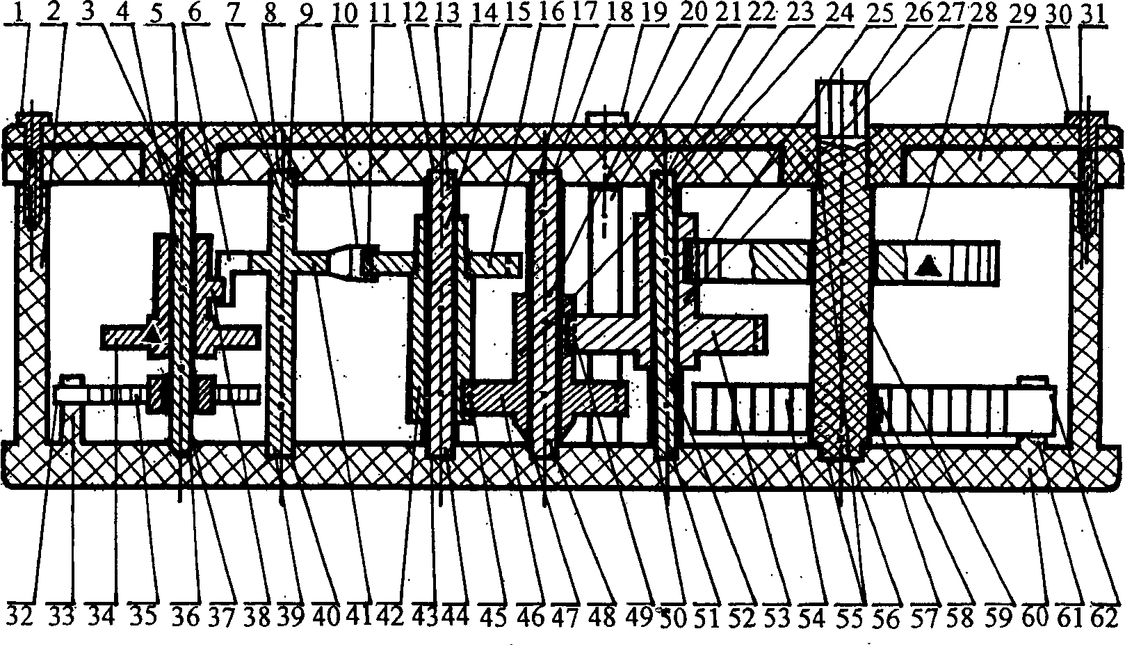
[0014] Below in conjunction with embodiment and accompanying drawing, the present invention will be further described.

[0015] Such as figure 1As shown, the head gear shaft 59 passes through the shaft end 26 and synchronously mechanically connects the tooth-changing series head gear 28 with the shaft end 56. The spring hook 57 is inserted into the mainspring 54 and the inner end 58 of the mainspring. Wheel, two wheel shafts 52 pass through the two small gears 27 and two large gears 53 of the interconnected body with the shaft end 22 or 51; 24 and three big gears 46 form the three wheels, the final wheel shaft 15 passes through the final gear 42 and the escape wheel 16 formed by the mutual synchronous mechanical connection with the shaft end 13 or 44, the teeth 11 of the escape wheel, the upper Splint 29, lower splint 60, shaft holes 12 and 43, shaft holes 18 and 47, shaft holes 23 and 50, shaft hole 55, splint top posts 21 and 31, screws 19 and 30, clockwork outer end 62, cl...


PUM


Abstract

Frequency conversion inseries balance wheel or balance wheel-hairspring module in hairspring frequency conversion series, and headgear in variable teeth series or head sheave in variable headgear series is adopted in system of traveltime. Under precondition of not changing integral structure of system and relevant technical data, changing round rotation angle position of end wheel by altered actual number of teeth of headgear, and changing oscillation frequency of balance wheel-hairspring module by altered inertia of balance wheel form basic timing quantity of mechanical timer in mutual cooperation series of balance wheel and headgear. Advantages are: enriching production specifications, and shortening production cycle.

Description

Technical field: [0001] The invention relates to a mechanical clock / timer, in particular to a mechanical timer whose product specification is determined by the basic timing quantity of the balance wheel head gear mutual cooperation series. Background technique: [0002] The structure and technical processing method of the existing mechanical timer still remain at the level of original technology so far, and the specifications of the product are extremely monotonous. [0003] In terms of product structure, although the number of teeth of each paired gear, the ratio of paired gears of each paired gear set, the number of total rotation cycles of the last wheel of the transmission gear group, the number of teeth of the escape wheel, and the total cumulative rotation of the teeth of the escape wheel The number of teeth, swing frequency, basic timing amount, selected timing amount setting range and other related production technical data are different among different manufacturers...

Claims


Application Information

Patent Timeline
IPC IPC(8): H01H43/10G04F3/02H01H43/02
Inventor 徐国林
Owner 徐国林
Why Eureka
Try Eureka