Container checking system with CT fault scanning function
A technology of tomography and inspection system, applied in the direction of measuring devices, instruments, scientific instruments, etc., can solve the problems of limiting the accuracy of inspection of complex containerized goods, unable to obtain tomographic images, etc., to achieve reasonable design, accurate inspection results, and reduced The effect of floor space
- Summary
- Abstract
- Description
- Claims
- Application Information
AI Technical Summary
Problems solved by technology
Method used
Image

Examples
Embodiment Construction
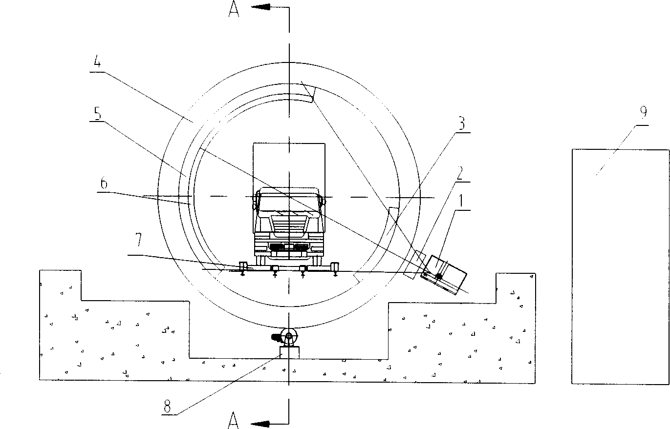
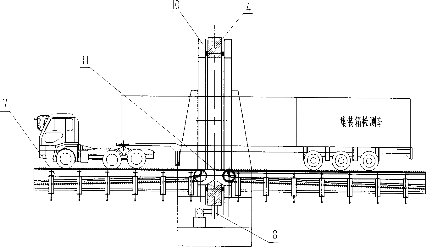
[0014] see figure 1 with figure 2 , the present invention includes a radiation source 1 using a linear electron accelerator or an isotope, a corrector 2, a front collimator 3, a rear collimator 6, a detector array 5 and a transport device 7 that can be loaded with a container inspection vehicle for reciprocating linear motion and A remote control device 9 equipped with an image acquisition module, an operation inspection module, and an electrical control module. The conveying device 7 of the plate type conveyor chain structure carried by multiple rows of cylindrical rollers that can be loaded with container inspection vehicles is composed of two parts and forms an intermittent structure, and a ring that allows container inspection vehicles to pass is arranged in the longitudinal direction of the intermittent gap 11 Shaped rotating frame 4. The outer side of the circular rotating frame 4 fixes the radiation source 1 and the corrector 2 facing the radiation source 1, and the ...
PUM
 Abstract
Description
Claims
Application Information
 - R&D
- Intellectual Property
- Life Sciences
- Materials
- Tech Scout
- Unparalleled Data Quality
- Higher Quality Content
- 60% Fewer Hallucinations
Browse by: Latest US Patents, China's latest patents, Technical Efficacy Thesaurus, Application Domain, Technology Topic, Popular Technical Reports.
© 2025 PatSnap. All rights reserved.Legal|Privacy policy|Modern Slavery Act Transparency Statement|Sitemap|About US| Contact US: help@patsnap.com