Liquid crystal device, liquid crystal display, and liquid crystal projector

A liquid crystal display and liquid crystal device technology, which is applied in the direction of projection devices, static indicators, instruments, etc., can solve the problems of increased steps for connecting flexible cables, restrictions on the shape of the package, and restrictions on connection accuracy, etc., to achieve enlarged manufacturing process margins, Effects of improving productivity and reducing compression ratio

Inactive Publication Date: 2006-06-07
SONY CORP
View PDF2 Cites 15 Cited by
  • Summary
  • Abstract
  • Description
  • Claims
  • Application Information

AI Technical Summary

Problems solved by technology

However, this method has considerable disadvantages, such as limitations in the shape of the package body, an increase in steps for connecting the flexible cable, and limitations in connection accuracy.

Method used


Image

  • Liquid crystal device, liquid crystal display, and liquid crystal projector
  • Liquid crystal device, liquid crystal display, and liquid crystal projector
  • Liquid crystal device, liquid crystal display, and liquid crystal projector

Examples


Embodiment Construction

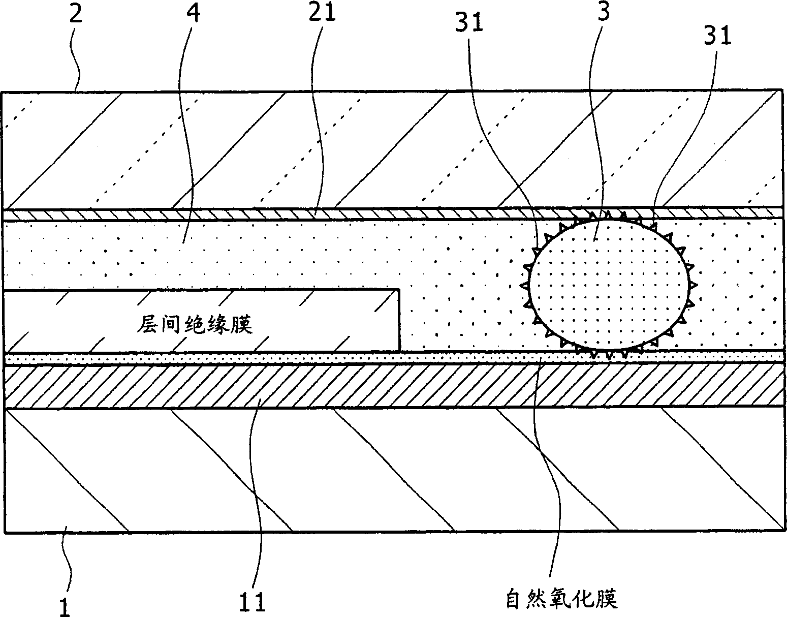
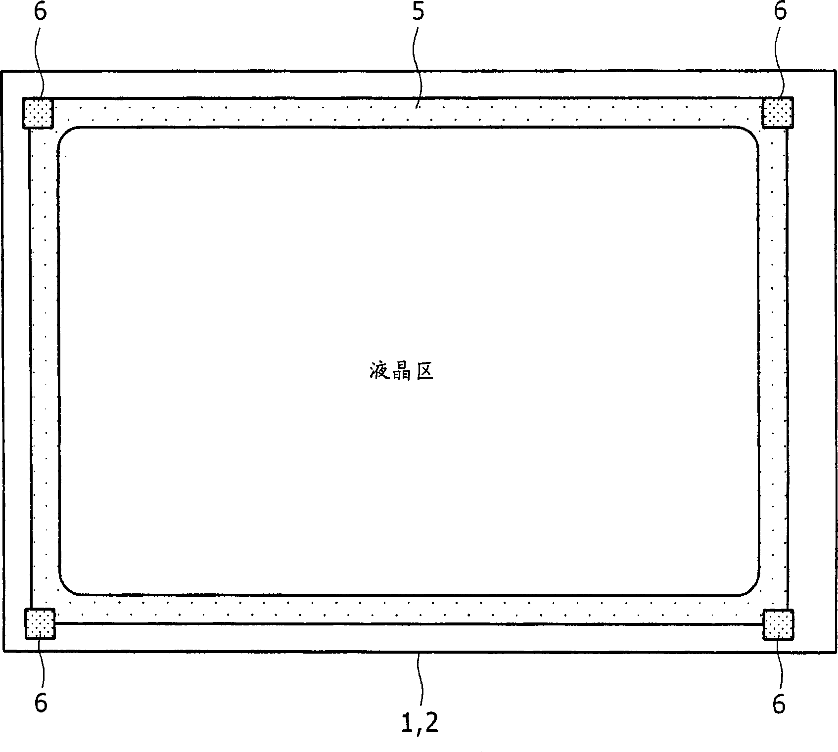
[0015] Now, an embodiment of the present invention will be described below based on the drawings. figure 1 is a schematic cross-sectional view for illustrating a liquid crystal display according to the present invention. Specifically, the liquid crystal display has a configuration in which a silicon drive substrate 1 and a glass substrate 2 are used as a pair of substrates disposed opposite to each other, the substrate 1 and the substrate 2 are bonded to each other with a predetermined distance therebetween, and the liquid crystal (not shown) out) inserted in between.

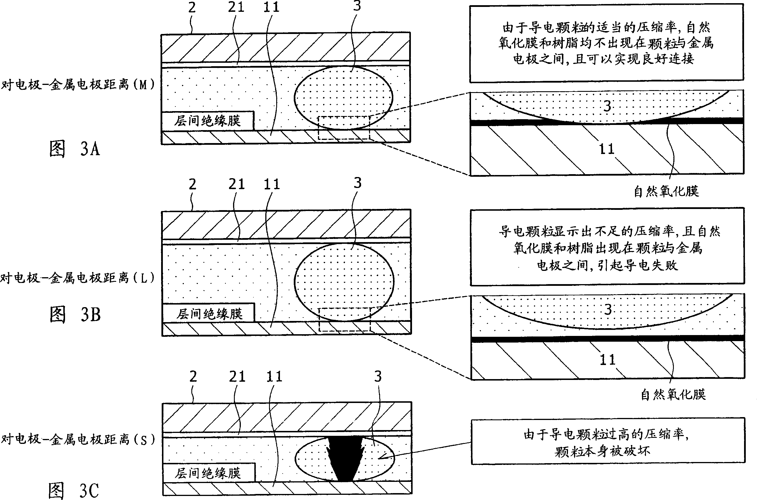
[0016] The silicon drive substrate is provided with a drive substrate side electrode (first electrode) 11 for supplying a voltage to a counter electrode (second electrode) 21 formed on the glass substrate 2 and for communication between the substrate side electrode 11 and the counter electrode 21. Conductivity, the conductive particles 3 are sandwiched between the silicon drive substrate 1 and the glass substr...


PUM


Abstract

A liquid crystal device comprising: a liquid crystal arranged between a pair of substrates (1,2) disposed opposite to each other; a driving electrode (11) on a surface of one of the substrates, made of silicon (1); a counter electrode (21) provided on a surface of the other substrate, made of glass (2) for driving the liquid crystal; and conductive particles (3) clamped between the substrates, to provide an electrical connection between the driving electrode and the counter electrode, wherein the conductive particles (3) are each provided with projections (31), i.e protrusions or asperities, in the surface thereof. The projections (31) improve the electrical contact on compression by breaking surface oxides and displacing resin material of the seal in which the particles are embedded. The conductive particles may be used in transmissive LCDs having glass substrates. Moreover the liquid crystal device may be used in LCD projection systems. The conductive particles (3) may consist of resin spheres which have been coated with a metal. When pressed between the substrates they are elastically deformed. The diameters of the particles are arranged to be in a range of 5 to 40% greater than the gap between the substrates. Furthermore, particles having at least two kinds of diameters may be used. This allows an optimum contact to be achieved even in the presence of cell-gap variations.

Description

technical field [0001] The present invention relates to a liquid crystal device, a liquid crystal display, and a liquid crystal projector in which liquid crystals are interposed between a pair of substrates disposed opposite to each other and driven by voltage supplied thereto from electrodes. Background technique [0002] In recent years, with the progress of higher definition, smaller size and higher brightness in liquid crystal projectors, reflective liquid crystal display as can be designed in smaller size and higher definition and is expected to show efficient light utilization Displays have received a lot of attention and have been put into practical use. A reflective liquid crystal display is an active type reflective liquid crystal display having a configuration in which a glass substrate provided with a transparent electrode is provided on one side, and a silicon substrate composed of, for example, a C-MOS (Complementary Metal Oxide Semiconductor) semiconductor circ...

Claims


Application Information

Patent Timeline
Patent Type & Authority Applications(China)
IPC IPC(8): G02F1/133G03B21/00G09G3/20
CPCG02F1/1339G02F1/13396G02F1/1345G02F2201/12
Inventor 上岛正弘
Owner SONY CORP
Why Eureka
Try Eureka