
Data authentication circuit, battery pack and portable electronic device

A technology for data authentication and battery assembly, applied in battery pack components, data exchange chargers, circuits, etc., can solve problems such as the increase in the number of components and the expansion of the installation area, and achieve the effect of suppressing adverse effects

Inactive Publication Date: 2006-06-07
RENESAS ELECTRONICS CORP
View PDF1 Cites 7 Cited by
  • Summary
  • Abstract
  • Description
  • Claims
  • Application Information

AI Technical Summary

Problems solved by technology

In this case, an increase in the number of parts and an expansion of the mounting area will result.

Method used


Image

  • Data authentication circuit, battery pack and portable electronic device
  • Data authentication circuit, battery pack and portable electronic device
  • Data authentication circuit, battery pack and portable electronic device

Examples


Embodiment 1

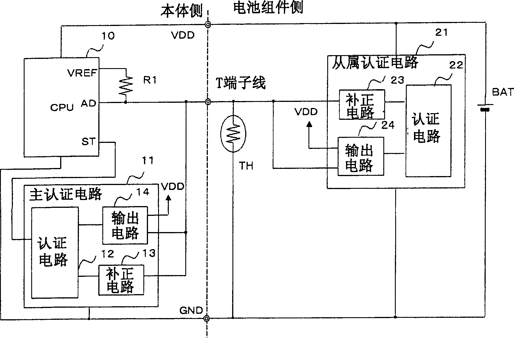
[0023] figure 1 It is a block diagram showing the configuration of the battery pack and the portable electronic device according to the first embodiment of the present invention. in figure 1 Among them, a portable electronic device (main body side) has a CPU 10, a main authentication circuit 11, and a resistor R1. On the other hand, on the battery pack side, a sub-certification circuit 21, thermistor TH, and battery BAT are provided. In addition, portable electronic devices are devices such as mobile phones, portable information terminals (including composite information terminals such as digital still cameras and digital video camera functions), and various circuits that enable the portable electronic devices to function are mounted on the body side of the device. , But it has nothing to do with the present invention, so its description is omitted. Also, on the battery pack side, in addition to the above-mentioned subordinate authentication circuit 21, thermistor TH, and batte...

Embodiment 2

[0050] Figure 6 It is a block diagram showing the structure of a battery pack and a portable electronic device according to the second embodiment of the present invention. in Figure 6 Among them, the portable electronic device (main body side) has a CPU 10a, a main authentication circuit 11a, a resistor R1, switches S1, and S2. On the other hand, the battery pack side has an authentication circuit 22a, a thermistor TH, a voltage adjustment circuit 25, a comparator 26, an inverter circuit INV, and switches S3 and S4. Here, the voltage adjustment circuit 25 and the comparator 26 constitute a potential correction circuit 23a. In addition, as the components constituting the subordinate authentication circuit on the battery side, the authentication circuit 22a, the voltage adjustment circuit 25, the comparator 26, the inverter circuit INV, and the switches S3 and S4 are included. In addition, on the main body side, as in the first embodiment, various circuits and the like for enabli...


PUM


Abstract

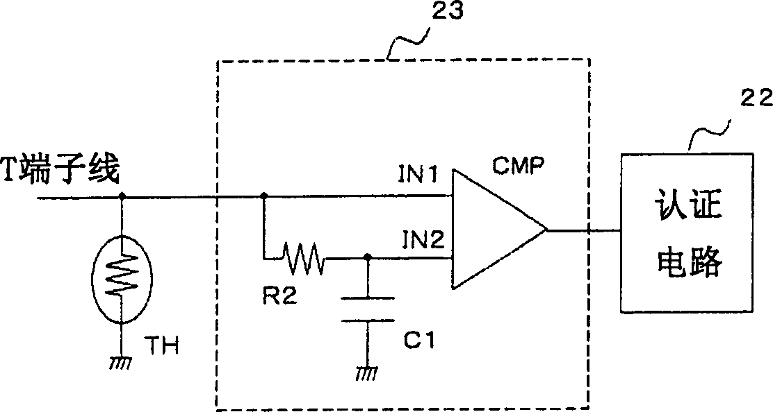
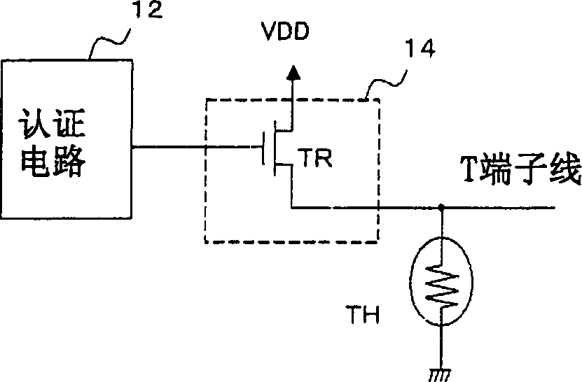
An authentication circuit capable of suppressing malfunctions of the authentication circuit for authenticating a battery pack. The signal line (T terminal line) for supplying the intermediate potential of power supply and ground and reading the potential of the thermistor TH for temperature detection is also used as a transmission line for data transmission and reception between the battery pack and the main unit. The master authentication circuit (11) and the slave authentication circuit (21) each have a potential correction circuit (13, 23) connected to a signal line via a voltage comparison circuit. The potential correction circuit (13, 23) is configured to correct the signal applied to the signal line to be greater than or less than the voltage in the indeterminate region, and output it to the input terminal of the authentication circuit (12, 22), so that the voltage in the indeterminate region is not applied to the input terminal. . During authentication, the output circuits (14, 24) alternately superimpose authentication information on the signal lines, and the potential correction circuits (23, 13) respectively receive and perform authentication.

Description

Technical field [0001] The present invention relates to a data authentication circuit, a battery assembly and a portable electronic device, and in particular to a battery assembly, a portable electronic device with a temperature detection function and an authentication function, and a data authentication circuit used in the same. Background technique [0002] In portable electronic devices such as mobile phones, battery packs equipped with batteries that supply power to the main body are generally used. When the battery cannot be fully charged, the entire battery assembly can be replaced and the electronic device can be used continuously. Here, as the battery, a rechargeable secondary battery such as a lithium ion battery is used, and the overcharge prevention circuit and the overdischarge prevention circuit are integrally assembled to form a battery module, which is a general situation. When the usable time of these secondary batteries is shortened (commonly known as the battery...

Claims


Application Information

Patent Timeline
Patent Type & Authority Applications(China)
IPC IPC(8): H01M10/48H01M2/10H01M2/34H01M10/42H04Q7/20
CPCH01M10/4207H01M10/4221H01M10/425H01M10/482H02J7/00036H02J7/00047Y02E60/10
Inventor 新家东
Owner RENESAS ELECTRONICS CORP
Learn More