Dptical receiving machine

An optical receiver and light-receiving technology, which is applied in electromagnetic receivers, optical fiber transmission, electromagnetic transceivers, etc., can solve the problems of increased output amplitude, difficulty in realizing digital output receivers, and enlargement

Inactive Publication Date: 2004-09-08
SHARP KK
View PDF0 Cites 9 Cited by
  • Summary
  • Abstract
  • Description
  • Claims
  • Application Information

AI Technical Summary

Problems solved by technology

Therefore, the (dV / dt) of the parasitic current I=C×(dV / dt) becomes large, and it is easy to operate incorrectly
Moreover, even if it is adjusted so that there is no misoperation when the power supply voltage is 3V, when the power supply voltage is 5V, tr and tf become shorter, the output amplitude increases, and the parasitic current becomes larger, resulting in misoperation
In addition, if tr and tf are adjusted so that malfunction does not occur when the power supply voltage is 5V, if the power supply voltage becomes 3V, tr and tf will be delayed, the speed of the signal that can be transmitted is limited, and it is difficult to realize the operating power supply voltage range wide high-speed digital output receiver
[0041] In addition, according to Japanese Patent Publication No. 3018541 (issue date: March 13, 2000), an output circuit that switches the slew rate of the output in two stages based on an external slew rate control signal is disclosed. Among them, since the slew rate of the output can only be controlled in 2 stages, it is very difficult to control the slew rate very finely within the range that can suppress malfunction

Method used


Image

  • Dptical receiving machine
  • Dptical receiving machine
  • Dptical receiving machine

Examples


Embodiment Construction

[0066] An embodiment of the present invention will be described below with reference to FIGS. 1 to 10 .

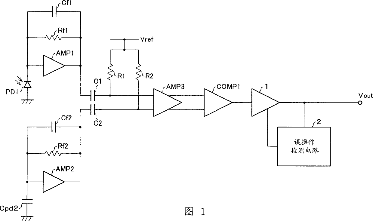
[0067] FIG. 1 is a circuit diagram showing a schematic configuration of an optical receiver of this embodiment. The optical receiver is provided with a photodiode (photoelectric conversion element) PD1 that receives an optical signal transmitted through an optical fiber, and a signal processing circuit that performs signal processing based on an output from the photodiode PD1. The photodiode PD1 and the signal processing circuit are integrated on one chip to form an optoelectronic integrated circuit (OEIC).

[0068] (Circuit structure of optical receiver)

[0069] First, the circuit configuration of the above-mentioned optical receiver will be described. The output from photodiode PD1 is connected to the input of amplifier AMP1. For this amplifier AMP1, a capacitor Cf1 and a resistor Rf1 are connected in parallel. Thus, the output of amplifier AMP1 is connected to capa...


PUM


Abstract

A photoreceptor is provided with an erroneous operation detection circuit for monitoring an output signal supplied from a slew rate variable output stage. The erroneous operation detection circuit performs such controls that a slew rate of output is decreased within a range in which a transmission speed of the slew rate variable output stage is not decreased. With this arrangement, it is possible to inhibit adverse effect on the output signal due to a parasite current caused between an output terminal of the photoreceptor and photoelectric converting means, such as a photodiode.

Description

technical field [0001] The present invention relates to an optical receiver for converting an optical signal into a digital electric signal and outputting it for applications such as optical fiber-linked digital audio. In particular, it relates to an optical receiver having an optoelectronic integrated circuit called an OEIC (Optoelectronic IC) integrating a light receiving element and a signal processing circuit on one chip. Background technique [0002] Fig. 11 is a block diagram showing a schematic configuration of a typical prior art optical receiver for optical fiber used in digital audio. In this optical receiver, a photodiode PD11 that receives an optical signal transmitted through an optical fiber and a signal processing circuit that performs signal processing based on an output from the photodiode PD11 are provided. The photodiode PD11 generates a current signal proportional to the intensity of the light signal. The photocurrent detected by the photodiode PD11 is ...

Claims


Application Information

Patent Timeline
Patent Type & Authority Applications(China)
IPC IPC(8): H03F3/08G08C19/36H01J40/14H04B10/07H04B10/2507H04B10/40H04B10/50H04B10/60H04B10/67H04B10/69H04L25/02
CPCH03F2200/78H03F2203/45544H03F3/087H03F3/45475H03F2203/45136H03F2203/45664
Inventor 清水隆行村田武士
Owner SHARP KK
Why Eureka
Try Eureka