

Apparatus for controlling motor
一种控制单元、电流的技术,应用在电机的装置领域,能够解决旋转负载变大、变大等问题
- Summary
- Abstract
- Description
- Claims
- Application Information
AI Technical Summary
Problems solved by technology
Method used
Image

Examples
no. 1 example
[0042] will refer to Figures 1 to 5 A first embodiment of the present invention is described.
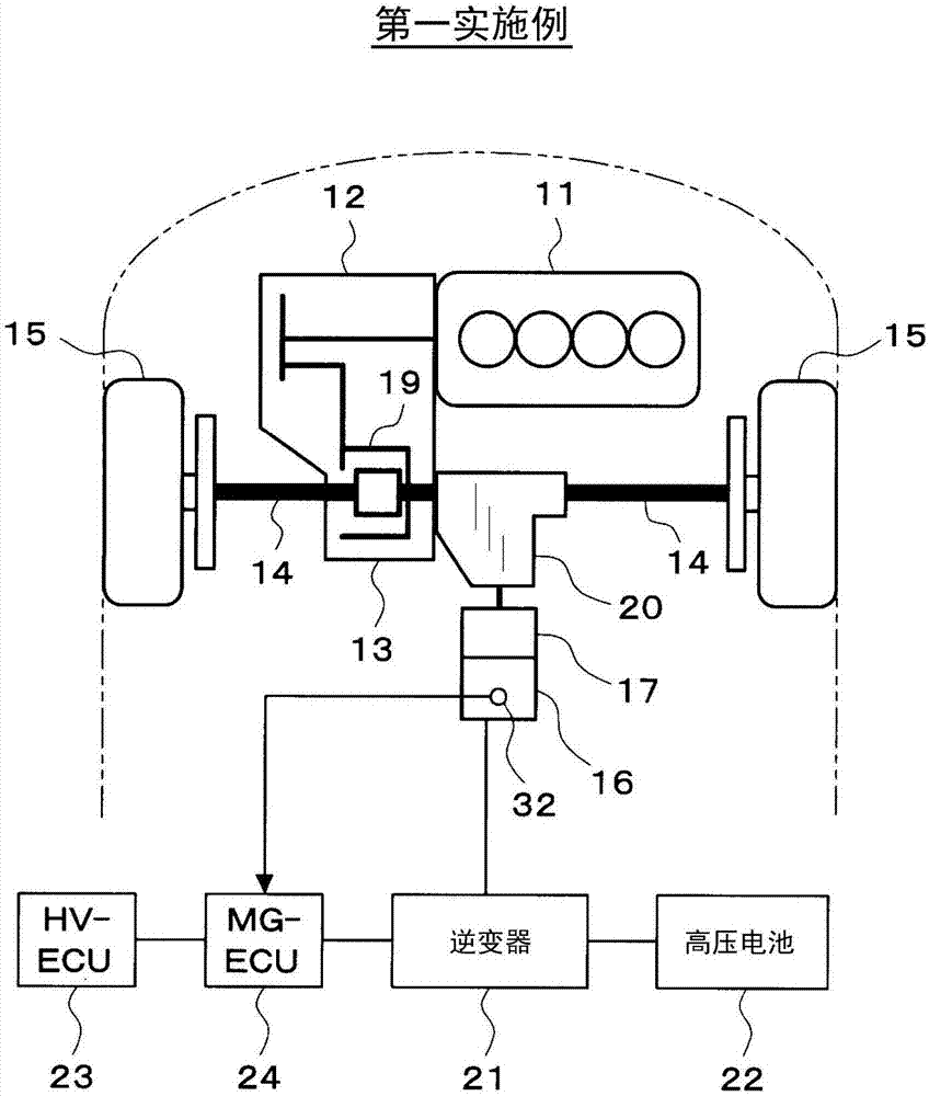
[0043] First refer to figure 1 , a schematic configuration of a control system of a hybrid vehicle will be described.
[0044] An engine 11 serving as a power source of the vehicle and a transmission 12 connected to the engine 11 are mounted on the front of the vehicle. The transmission 12 is a mechanical transmission, and may be a multi-stage transmission that switches gears in stages between a plurality of gears, or may be a continuously variable transmission (so-called CVT) that continuously changes gears. The engine 11 and the transmission 12 are arranged laterally such that the axial direction of the output shaft of the engine 11 (ie, the crankshaft) becomes the left-right direction of the vehicle. The power of the output shaft of the engine 11 is transmitted to the transmission 12 , and the power of the output shaft of the transmission 12 is transmitted to the drive shaft ...
no. 2 example
[0076] Next, we will use Figure 6 to Figure 9 A second embodiment of the present invention will be described. However, descriptions of portions substantially the same as or similar to those of the first embodiment described above will be omitted or simplified, and portions different from the first embodiment described above will be mainly described.
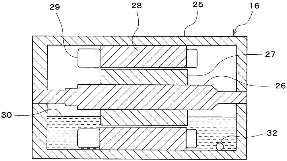
[0077] In the second embodiment, the MG-ECU 24 executes Figure 9 The mode switching routine of , thereby switching the normal mode and the warming mode as follows. When the temperature of the cooling oil 30 detected by the cooling oil temperature sensor 32 is the predetermined value A (ie, the first predetermined value) or below, the normal mode is switched to the heating mode, and when the cooling oil temperature detected by the cooling oil temperature sensor 32 is The temperature raising mode is switched to the normal mode when the temperature of the oil 30 is a predetermined value B higher than the predetermined value A (i...
no. 3 example
[0096] Next, we will use Figure 10 to Figure 12 A third embodiment of the present invention will be described. However, descriptions of parts substantially the same as or similar to those of the second embodiment described above will be omitted or simplified, and parts different from the second embodiment described above will be mainly described.
[0097] In this third embodiment, if Figure 10 As shown, a coil temperature sensor 38 for detecting the temperature of the coil 29 is provided in the housing 25 of the MG 16 . like Figure 11 As shown, there is a correlation between the temperature of the coil 29 and the temperature of the cooling oil 30 .
[0098] Therefore, in this third embodiment, the MG-ECU 24 executes Figure 12 The mode switching routine of , thereby switching the normal mode and the warming mode as follows. When the temperature of the coil 29 detected by the coil temperature sensor 38 is a predetermined value C (that is, the third predetermined value) ...
PUM
 Abstract
Description
Claims
Application Information