Heat pipe

A heat pipe and heat technology, applied in the field of heat pipes, can solve the problems of low thermal conductivity and reduced thermal conductivity, and achieve the effect of improving thermal conductivity

Inactive Publication Date: 2006-06-14
LEJIN ELECTRONICS KUNSHAN COMPUTER CO LTD
View PDF0 Cites 11 Cited by
  • Summary
  • Abstract
  • Description
  • Claims
  • Application Information

AI Technical Summary

Problems solved by technology

Therefore, relatively speaking, the original heat pipe has the problem of low heat conduction efficiency.
[0013] In addition, the circulating fluid in the evaporating part 7 relies on the heat from the heat source for state transformation and reaches a boiling state. However, if the temperature is too high, the circulating fluid will boil in a film shape after reaching boiling, which leads to the problem of reduced heat transfer efficiency.

Method used


Image

  • Heat pipe
  • Heat pipe
  • Heat pipe

Examples


Embodiment Construction

[0033] Embodiments of the heat pipe of the present invention will be described in detail below with reference to the accompanying drawings.

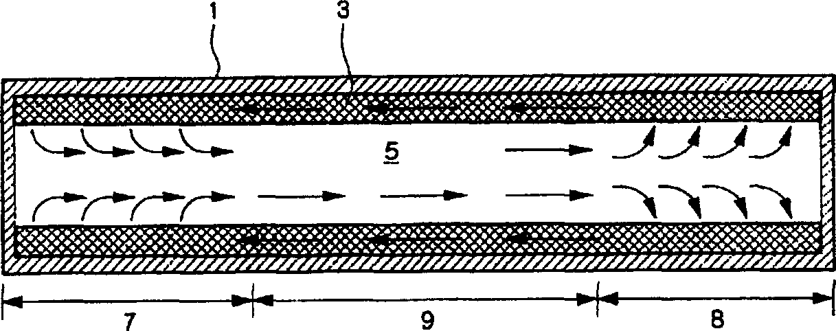
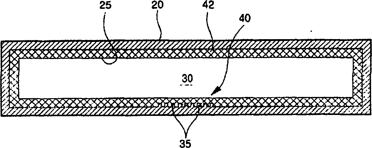
[0034] exist figure 2 The ideal working state of the heat management structure adopting the present invention is shown in a simplified cross-sectional view. exist image 3 A side view is used to show the composition of the middle part of the working state of the heat pipe of the present invention.

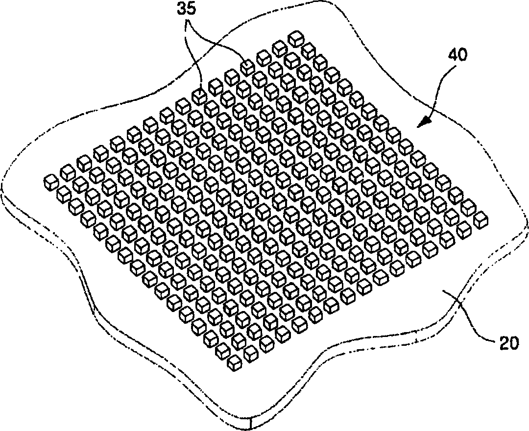
[0035] As shown in the figure, the appearance of the heat pipe is box-shaped. The box-shaped casing 20 of the heat pipe is in the shape of an oblate plate, and its cross section is in the shape of a circular tube or an oval tube. The box-shaped housing 20 is made of high-efficiency heat-conducting material. Metal materials such as copper or aluminum.

[0036] The inner wall of the box-shaped housing 20 is provided with capillary structures 25 . The capillary structure 25 is a porous structure capable of generating capillary force. The...


PUM


Abstract

The invention relates to heat pipe. It is set evaporating part and condensing part. It includes the following structure: circulation fluid storage space, box type shell, capillary structure in shell inner wall, passage supplied for gas state circulation fluid to flow, and heat exchange unsmooth in the evaporating part. It has the advantages that it can maximize exchange area to relatively increase heat exchange efficiency; it can prevent bubble to increase heat exchange efficiency when the phase of the heat tube is changed.

Description

(1) Technical field [0001] The present invention relates to heat pipe technology, in particular to a heat pipe that utilizes the phase transition of the fluid state to release the heat stored in the fluid from a heat source, thereby achieving the purpose of heat conduction. (2) Background technology [0002] The so-called heat pipe is a component that uses the latent heat required by the fluid in the process of its state mutual conversion to make the fluid conduct heat from a place with a high heat density to a place with a low heat density. [0003] Because it utilizes the principle of mutual conversion of fluid states, the thermal conductivity of the heat pipe is higher than that of any known metal. [0004] In fact, the heat pipe that circulates inside has a thermal conductivity hundreds of times higher than that of silver and copper, which have very high thermal conductivity, in the normal temperature range. [0005] The shape of this heat pipe is generally divided into...

Claims


Application Information

Patent Timeline
Patent Type & Authority Applications(China)
IPC IPC(8): F28D15/04
Inventor 许哲豪
Owner LEJIN ELECTRONICS KUNSHAN COMPUTER CO LTD
Why Eureka
Try Eureka