
Network layered model and interlaminar mapping method for optical transmission communication network

A communication network and network layering technology, which is applied in the layer-to-layer mapping of the layered model and the network layered model field of the optical transmission communication network, to achieve the effect of saving network construction costs, optimizing configuration, and meeting the requirements of service quality

Active Publication Date: 2006-06-21
CHINA INFORMATION TECH DESIGNING & CONSULTING INST
View PDF0 Cites 6 Cited by
  • Summary
  • Abstract
  • Description
  • Claims
  • Application Information

AI Technical Summary

Problems solved by technology

In view of this demand, the design of optical transmission communication network needs to provide a new design method, which is used to describe the composition of the network more realistically, and realize the multi-layer joint planning and design of optical transmission communication network to meet the needs of modern optical transmission communication. However, there have been no reports on this

Method used


Image

  • Network layered model and interlaminar mapping method for optical transmission communication network
  • Network layered model and interlaminar mapping method for optical transmission communication network

Examples


Embodiment 1

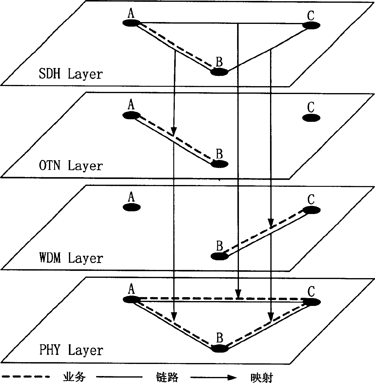
[0028] As shown in Figure 1, the network layered model for the optical transmission communication network of the present invention comprises the following steps:

[0029] In the first step, the network is divided into the following four layers:

[0030] a, optical synchronous transport network (SDH) layer: this layer is used to describe the optical transmission communication network composed of equipment that meets SDH related standards, and this layer has basic attributes such as nodes, links, and services; the optical synchronous transport network ( The SDH layer is divided into client layer, SDH layer, and physical layer from top to bottom; the SDH layer is divided into channel layer and section layer from top to bottom.

[0031] b. Optical Transport Network (OTN) layer: This layer is used to describe the optical transmission communication network composed of equipment conforming to OTN-related standards. This layer has basic attributes such as nodes, links, and services; t...

Embodiment 2

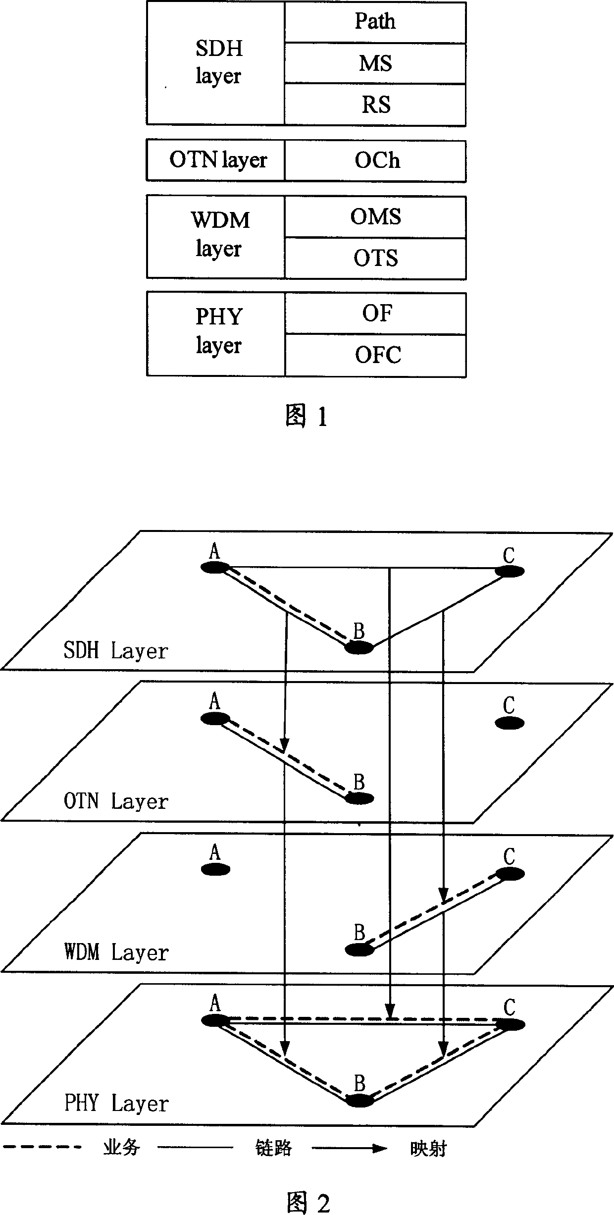
[0041] As shown in Figure 2, in order to further describe the present invention in detail, an actual network is taken as an example here, and the goal of function realization is to plan and design the optical transmission communication network shown in Figure 2 using the method of the present invention. The implementation steps are as follows:

[0042] The first step is to divide the network into four layers according to the current situation and requirements of the network. in:

[0043] SDH layer: nodes are A, B, C; links are A-B, B-C, C-A; services are A-B.

[0044] OTN layer: Nodes are A, B, and C; links are A-B.

[0045] WDM layer: nodes have A, B, C; links have B-C.

[0046] PHY layer: Nodes are A, B, and C; links are A-B, B-C, and C-A.

[0047] The second step is to perform inter-layer mapping on the links of each layer of the network. The binding relationship is as follows:

[0048] SDH layer: Link A-B is bound to OTN layer service A-B, link B-C is bound to WDM lay...


PUM


Abstract

The invention discloses a network layer model for OTCN, which comprises: first, dividing network into four layers top-bottom: a. SDH layer; b. OTN layer; c. WDM layer; and d. PHY layer; second, setting some node groups according to whether nodes in same city, same local station, and same floor; any node in one layer must in some node grouping, permitting s plurality of nodes in one layer to belong same group; there is matching relation among nodes of different layer but same group. This invention optimizes network resource configuration, and saves cost.

Description

technical field [0001] The invention relates to the field of optical fiber communication, in particular to a network layered model method for optical transmission communication network. The invention also relates to a layer-to-layer mapping method of the layered model. Background technique [0002] Optical transmission communication network planning and design refers to the determination of network topology, equipment configuration, relay bandwidth, business arrangement and other technical solutions in the construction of optical transmission communication network through a series of technical methods, so that it can solve the given business needs, and Satisfy constraints such as reasonable construction cost, feasible project implementation and convenient operation and maintenance. [0003] At present, the planning and design of the network in the field of optical transmission and communication is mostly at the system level, targeting chain and ring structures; the planning...

Claims


Application Information

Patent Timeline
Patent Type & Authority Applications(China)
IPC IPC(8): H04L12/24H04L29/08
Inventor 王光全程立勋何磊陆月明李慧
Owner CHINA INFORMATION TECH DESIGNING & CONSULTING INST
Learn More