Low temp. sintering niobate microwave dielectric ceramic and preparation process thereof

A microwave dielectric ceramic and low-temperature sintering technology, applied in the field of dielectric ceramic materials, can solve the problems of small Q f value, poor comprehensive performance, difficult to meet high frequency, high reliability, etc.

Inactive Publication Date: 2006-06-28
WUHAN UNIV OF TECH
View PDF0 Cites 28 Cited by
  • Summary
  • Abstract
  • Description
  • Claims
  • Application Information

AI Technical Summary

Problems solved by technology

[0008] With the accelerated development of information technology, mobile communication systems are developing in the direction of high frequency, miniaturization, integration, and high reliability. The dielectric constant of the medium dielectric constant material system is low, and it is very easy to maintain the Q value without reducing the dielectric constant. It is difficult to meet the needs of further miniaturiza

Method used


Image

  • Low temp. sintering niobate microwave dielectric ceramic and preparation process thereof

Examples


Embodiment Construction

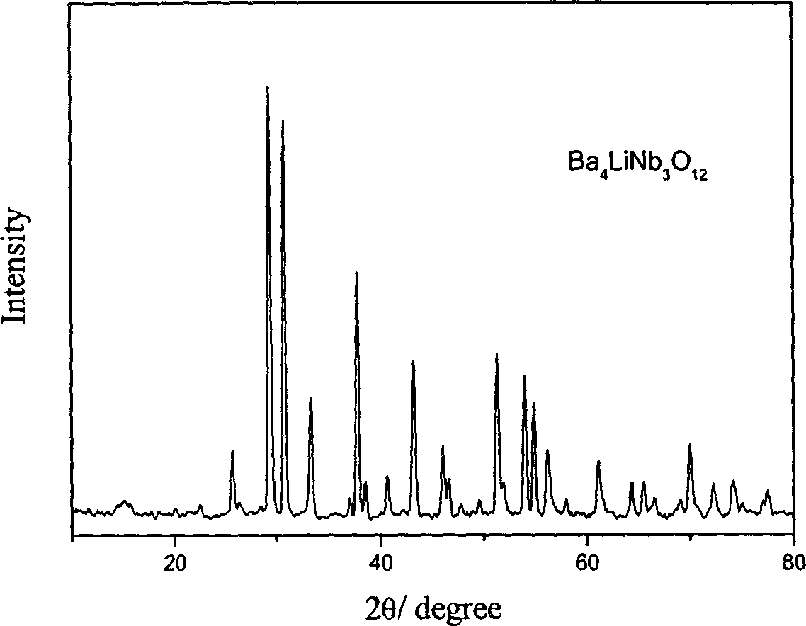
[0019] Table 1 shows several specific examples of the content of each component constituting the present invention and their microwave dielectric properties. Its preparation method is as described above, and the phase analysis of the ceramic sample after sintering is carried out by powder X-ray diffraction method, figure 1 For the X-ray diffraction pattern of Example 1, the evaluation of the microwave dielectric properties was carried out by the cylindrical dielectric resonator method.

[0020] The ceramics can be widely used in the manufacture of various dielectric resonators, filters and other microwave devices, and can meet the technical needs of mobile communication, satellite communication and other systems.

[0021] Elements such as Ca, Pb, etc., which have similar structures and chemical properties to Ba and Sr, and elements such as Ti, Sn, and Zr, which have similar structures and chemical properties to Nb, can also make dielectric ceramics similar to the crystal struc...


PUM


Abstract

The invention discloses a low temperature sintering niobate high frequency dielectric ceramic used in microwave component and ceramic capacitor or temperature compensating capacitor. The main phase of the ceramic is (Ba1-xSr x)4LiNb3-yTayO12, of which 0.00<=x<=1, 0.00<=y<=2. It is well sintering, low consumption, and high frequency dielectric constant could reach to 40-90.

Description

technical field [0001] The invention relates to a dielectric ceramic material, in particular to a dielectric resonator, a filter and other microwave components used at microwave frequencies, as well as the dielectric ceramic material of a ceramic capacitor or a temperature compensation capacitor and a preparation method thereof. Background technique [0002] Microwave dielectric ceramics refer to ceramics that are used as dielectric materials in microwave frequency band (mainly UHF, SHF frequency band) circuits and perform one or more functions. They are widely used as resonators, filters, and dielectric substrates in modern communications. Chips, dielectric waveguide circuits and other components are the key basic materials of modern communication technology. They have been used in portable mobile phones, car phones, cordless phones, TV satellite receivers, military radars, etc. It is playing an increasingly important role in the process of miniaturization and integration. ...

Claims


Application Information

Patent Timeline
IPC IPC(8): C04B35/01C04B35/495C04B35/622C04B35/64
Inventor 方亮张辉孟森森
Owner WUHAN UNIV OF TECH
Why Eureka
Try Eureka