Variable-speed device

A continuously variable transmission, the same technology, applied in the direction of components with teeth, belts/chains/gears, mechanical equipment, etc., can solve the problems of complex structure, low power, and troublesome control of the continuously variable transmission, and prolong the overhaul interval. Effectiveness of mileage, high average speed, ease of maintenance

Inactive Publication Date: 2006-06-28
吴志强
View PDF0 Cites 12 Cited by
  • Summary
  • Abstract
  • Description
  • Claims
  • Application Information

AI Technical Summary

Problems solved by technology

[0002] At present, the commonly used continuously variable transmissions are designed according to the principles of friction and hydrostatics, etc., and the power they can transmit is not large, and the efficiency is not high; In addition, these continuously variable transmissions are complex in structure, cumbersome to control, and need to be realized through expensive materials and precise manufacturing, so the cost is high

Method used


Image

  • Variable-speed device
  • Variable-speed device
  • Variable-speed device

Examples


Embodiment 1

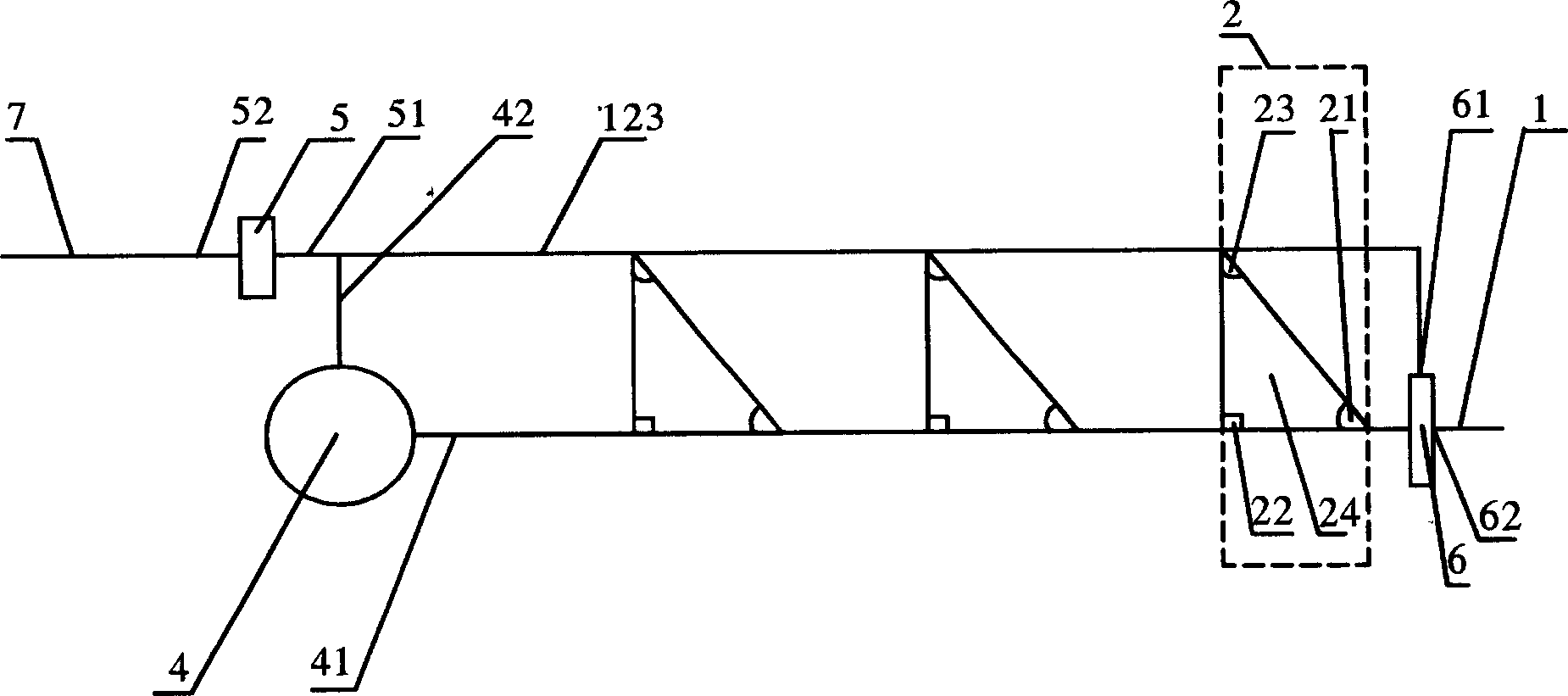
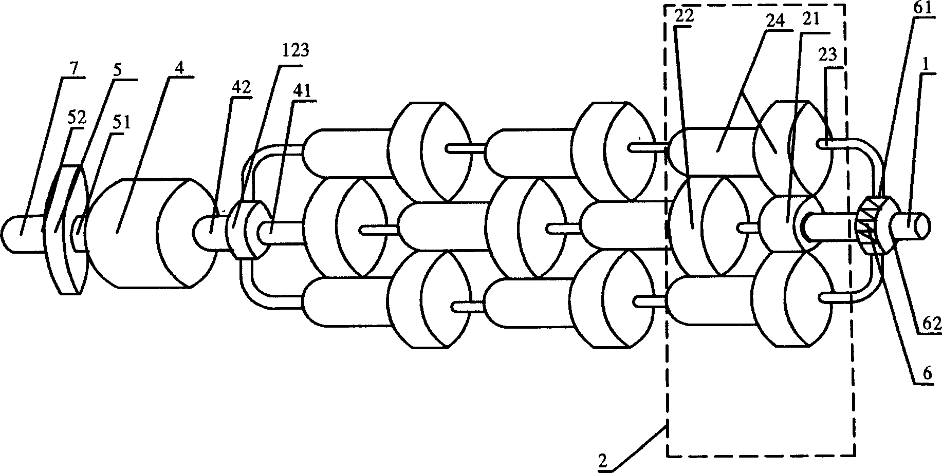
[0033] Such as figure 1 , figure 2 As shown in , a continuously variable transmission includes an input shaft 1, a controllable torque device 4, an empty reverse mechanism 5, a one-way clutch 6, and an output shaft 7, and the output end 62 of the one-way clutch 6 is connected to the input shaft 1 connection, the output end 42 of the controllable torque device 4 is connected with the input end 51 of the idle reverse gear mechanism 5, the output end 52 of the idle reverse gear mechanism 5 is connected with the output shaft 7, and three shafts are arranged between the input shaft 1 and the output shaft 7. A sequentially connected torque booster unit 2 composed of planetary rows with the same direction performance, said torque booster unit 2 includes input element 21, output element 22, common output element 23, planetary gear 24, the first torque booster unit 2 The input element 21 is connected with the input shaft 1, and the common output element 23 of each torque booster unit...

Embodiment 2

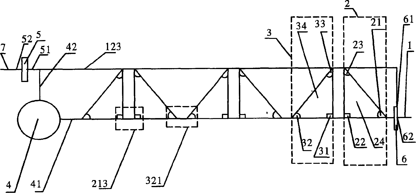
[0039] Such as image 3 , Figure 4 As shown in , it includes an input shaft 1, a controllable torque device 4, an idle reverse mechanism 5, a one-way clutch 6, and an output shaft 7. The output end 62 of the one-way clutch 6 is connected with the input shaft 1, and the controllable torque The output end 42 of the device 4 is connected with the input end 51 of the idle reverse gear mechanism 5, and the output end 52 of the idle reverse gear mechanism 5 is connected with the output shaft 7. The torque-increasing unit 2 composed of planetary rows with the same direction performance, each torque-increasing unit 2 is connected with a speed-up unit 3 composed of planetary rows with the same direction performance, and the speed-up unit 3 includes an input element 31, an output element 32. Common output element 33, planetary gear 34, the input element 21 of the first torque increasing unit 2 is connected with the input shaft 1, and the input elements 21 of the remaining torque incre...

Embodiment 3

[0046] Such as Figure 5 As shown in , this embodiment only changes the arrangement order of the torque increasing unit 2 and the speed increasing unit 3 that work together in the second embodiment, and its working principle and realized functions and effects remain unchanged.


PUM


Abstract

The invention provides a stepless speed changer, which can prolong service life of engine and drive system, and has simple structure, operation and control convenience, low cost and high energy-saving efficiency. And the key points of its technical solution: it comprises input shaft, controllable moment apparatus, empty reverse gear mechanism, clutch, and output shaft, where there are several moment increasing units composed of planetary gear sets connected in turn, where each moment increasing unit comprises input component, output component, common output component, and planetary gear, the input component of the first moment increasing unit is connected with the input shaft and the common output component is connected to the output end of the controllable moment apparatus and then connected to the input end of the empty reverse gear mechanism, and the output unit of the last moment increasing unit is connected with the input end of the controllable moment apparatus.

Description

technical field [0001] The invention belongs to the field of transmissions, more specifically, it is a transmission for various ground vehicles, ships, railway locomotives, engineering machinery, various aerospace, aircraft, metallurgy, mining, petroleum, chemical industry, light industry, food, textile , Lifting and transporting machinery, machine tools, robots and military CVTs. Background technique [0002] At present, the commonly used continuously variable transmissions are designed according to the principles of friction and hydrostatics, etc. The power it can transmit is not high, and the efficiency is not high; Expensive materials and sophisticated manufacturing are required to achieve this, and thus the high cost. Contents of the invention [0003] The invention overcomes the deficiencies of the prior art and provides a continuously variable transmission that prolongs the service life of the engine and the transmission system, has simple structure, convenient ope...

Claims


Application Information

Patent Timeline
Patent Type & Authority Applications(China)
IPC IPC(8): F16H61/00
Inventor 吴志强
Owner 吴志强
Why Eureka
Try Eureka