Thermal fatigue tester

A testing machine and thermal fatigue technology, applied in thermal analysis of materials, measuring devices, instruments, etc., can solve problems such as the influence of test results, and achieve the effect of accurate and reliable positioning and flexible operation

Inactive Publication Date: 2006-07-05
INST OF METAL RESEARCH - CHINESE ACAD OF SCI
View PDF0 Cites 25 Cited by
  • Summary
  • Abstract
  • Description
  • Claims
  • Application Information

AI Technical Summary

Problems solved by technology

This has a great influence on the test results

Method used


Image

  • Thermal fatigue tester
  • Thermal fatigue tester
  • Thermal fatigue tester

Examples


Embodiment 1

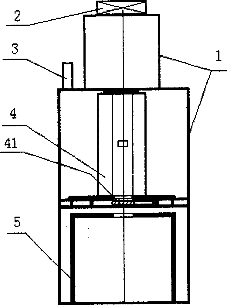
[0026] The structural diagram of the thermal fatigue testing machine is as follows figure 1 As shown, it is mainly composed of bracket (1), lifting system (2), control system (3), heating system (4) and cooling system (5), cooling system (5), heating system (4), control system ( 3) and the lifting system (2) are placed on the support (1) sequentially from bottom to top;

[0027] The bracket (1) is welded by angle iron,

[0028] The cooling system (5) consists of a water tank and a thermometer inserted into the water,

[0029] The heating system (4) consists of a resistance furnace, a sliding door (41) and a thermocouple inserted into the furnace,

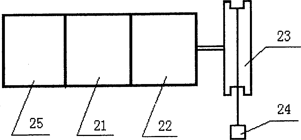
[0030] Lifting system (2) (see figure 2 ) Is composed of a motor (21) with a brake (25), a reduction box (22) and a wheel (23). The motor (21) realizes a transmission connection with the wheel (23) through the reduction box (22);

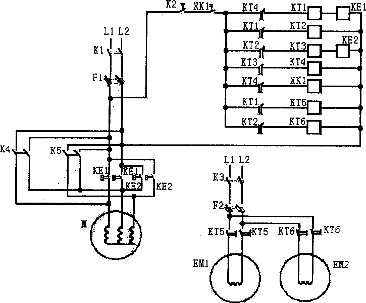
[0031] Control system (3) (see image 3 ) Mainly composed of motor (21) rise time control circuit, heat p...


PUM


Abstract

The invention provides a thermal fatigue tester, where a cooling system, a heating system, a control system and a lift system are arranged on a bracket; the cooling system is composed of a water tank and a thermometer inserted in the water, the heating system is composed of a resistance furnace, a slide gate and a thermocouple inserted in the resistance furnace, and the electric machine of the lift system drives a test piece through reduction gearbox and rotary table; the control system is composed of raising control circuit, heat insulating time control circuit, lowering control circuit, cooling time control circuit, slide gate control circuit, circulating counting control circuit and the like; the contacts of a raising time relay are in the heat insulating time control circuit and the power supply circuit of a slide gate closing electromagnetic relay; the contacts of a heat insulating time relay are in the lowering control circuit and the power supply circuit of a slide gate opening electromagnetic relay; the contacts of a lowering time relay are in the cooling time control circuit; the contacts of a cooling time relay are in the raising control circuit and the counting control circuit; the contacts of a counter are in the main circuit of the control system. The advantages: completely automatic, flexible to operate and accurate to locate.

Description

Technical field: [0001] The invention relates to material testing technology, especially material fatigue testing technology. Background technique: [0002] Thermal fatigue refers to the restriction of the free expansion or contraction of the material caused by temperature changes. As a result, thermal stress is generated within the material due to the restricted deformation. When the temperature changes repeatedly, this thermal stress also changes repeatedly, thus causing the material to be damaged. High-temperature alloys are mainly used to manufacture various high-temperature components of aviation turbine engines and various high-temperature components of aerospace rocket engines. They are essential key components for modern aviation and aerospace engines. In aviation and aerospace engines, high-temperature alloys work for a long time under the action of high temperature and complex stress at 600~1200℃, and the conditions are relatively harsh. Especially when the combustion c...

Claims


Application Information

Patent Timeline
Patent Type & Authority Applications(China)
IPC IPC(8): G01N3/60G01N25/00
Inventor 夏鹏成于金江孙晓峰侯贵臣刘源管恒荣胡壮麒
Owner INST OF METAL RESEARCH - CHINESE ACAD OF SCI
Why Eureka
Try Eureka