Shield wire, housing connected with same, connecting method thereof and shield wire unit

A wire and box technology, which is applied to power cables with shielding/conducting layers, conductive connections, and electrical component connections, etc., can solve the problems of 351 micro-cracks in the coating layer, heating of braided shielded wires, and increased resistance value. Achieving excellent results and good connection performance

Inactive Publication Date: 2006-07-12
HITACHI CABLE
View PDF1 Cites 13 Cited by
  • Summary
  • Abstract
  • Description
  • Claims
  • Application Information

AI Technical Summary

Problems solved by technology

As a result, the braided shielded wire 352 generates heat, and the resistance value of the connecting portion between the power supply box and the shielded wire may increase.
In

Method used


Image

  • Shield wire, housing connected with same, connecting method thereof and shield wire unit
  • Shield wire, housing connected with same, connecting method thereof and shield wire unit
  • Shield wire, housing connected with same, connecting method thereof and shield wire unit

Examples


Example Embodiment

[0086] Hereinafter, a preferred embodiment of the present invention will be described based on the drawings.

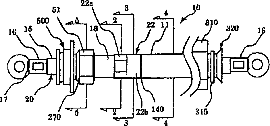
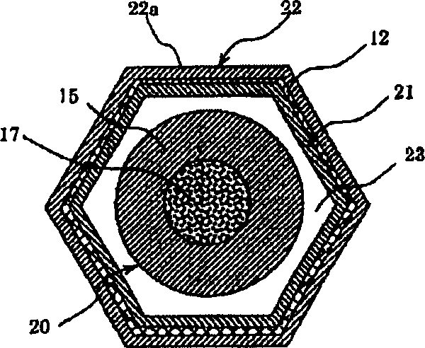
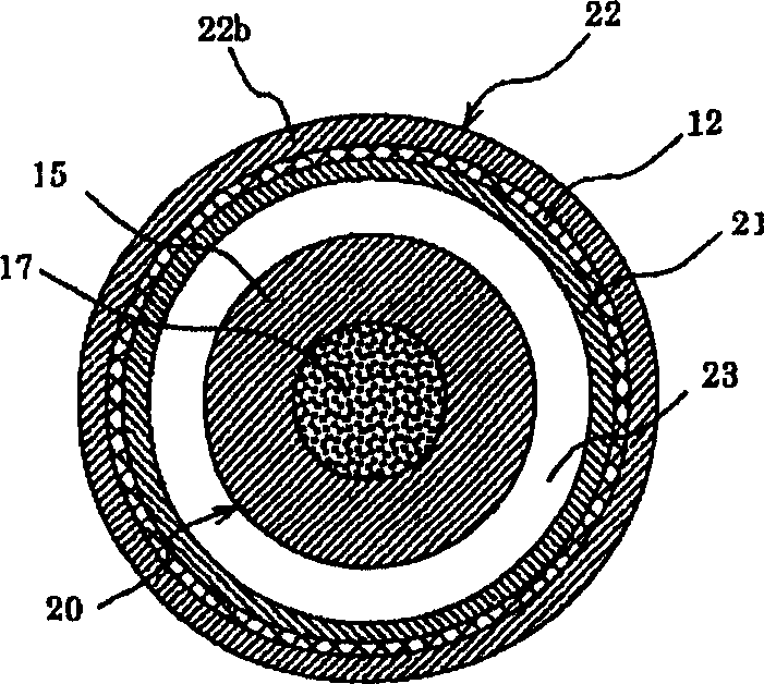
[0087] Such as figure 1 As shown, the shielded electric wire of the present embodiment is provided with a shielding member around the conductive body 20 formed of a conductor 17 made of a single wire material or a strand material covered by an insulator 15. The shielded electric wires are connected with connection terminals 16, 16 at both ends. One end ( figure 1 The connecting terminal 16 on the left side of the middle) is connected to, for example, one side of the inverter described later, and the other end ( figure 1 The connection terminal on the right side of the middle) is connected to, for example, a transmission device described later.

[0088] The shielding part is made up of Figure 6 The cylinder 50 shown and Picture 12 The illustrated metal pipe 11 is constructed. The cylinder 50 and the metal pipe 11 are butted and arranged, and the cylinder 50 and the me...


PUM


Abstract

To provide a shield wire excellent in bending property, shock resistant property, and heat resistant property, and to provide a box connected to the shield wire, a method of connecting the shield wire and the box, and a shield wire unit.The shield wire is composed of a wire body 20 formed by covering a conductor 17 made of single wire or stranded wire by an insulation body 15, and a shield member arranged at outer periphery of the wire body 20. The shield member is constituted of a cylinder 50 formed by successively arranging a braided shield 12 and an outer sleeve 22 around an inner sleeve 21, and a metal pipe 11 arranged so as to face the cylinder 50. The cylinder 50 is electrically connected to the metal pipe 11, and a pipe-shaped connection member 310 is fitted to a non-cylindrical side of the metal pipe 11. A connector member 500 having a flange part 502 is electrically connected to a non-metallic pipe side of the cylinder 50.

Description

technical field [0001] The present invention relates to shielded electric wires for supplying power to equipment, and more particularly to shielded electric wires for supplying power to various equipment in automobiles. Background technique [0002] The shielded electric wire has a braided shielded wire braided with copper wires, tinned copper wires, or the like having a wire diameter of several tens of μm to several hundreds of μm on the outside of the sheathed electric wire. By connecting both ends of the braided shielded wire to metal connectors and grounding the connectors, a protective effect against malfunction due to electromagnetic waves or the like can be obtained. [0003] In recent years, for automobiles, hybrid vehicles are gaining popularity, and the electrification of equipment is advancing rapidly. Therefore, in shielded wires used in various equipment of automobiles, etc., high voltage and high current are increasingly realized. In addition, with the popula...

Claims


Application Information

Patent Timeline
IPC IPC(8): H01R4/64H01R11/11H01R11/12H01B9/02H01B11/06H01R4/50H01R4/56H01R13/621H01R13/655
Inventor 鹫见享青山正义山下宣幸清水道晃冲川宽
Owner HITACHI CABLE
Why Eureka
Try Eureka