Heat pipe seal method

A sealing and heat pipe technology, applied in the field of heat pipe sealing, can solve problems such as increasing defective products, affecting product quality, and difficult operation, and achieve the effects of improving the good rate, reducing the time required for sealing, and increasing the heat conduction speed

Inactive Publication Date: 2006-07-19
THERMOKING TECH INT
View PDF0 Cites 3 Cited by
  • Summary
  • Abstract
  • Description
  • Claims
  • Application Information

AI Technical Summary

Problems solved by technology

[0003] The method of existing large heat pipe sealing is as figure 1 As shown, as shown in the figure, the opening end of the heat pipe 2 is pressurized by a machine to form a "one"-shaped flat seal 21, and then the flat seal 21 is cut off and welded on the truncated surface Sealing work; however, such a sealing method will cause the bonding strength and tightness of the sealing structure to be quite poor, so that the heat transfer fluid will easily flow out of the heat transfer tube 2, and correspondingly, air will easily enter the heat transfer tube 2, causing the heat transfer tube to 2. The number of defective products manufactured increases, and after the pipe material of the heat pipe 2 is deformed under pressure, the length of the flat pressure direction of the seal is obviously greater than the diameter of the heat pipe 2 itself. It is easy to be limited by the space configuration in assembly; moreover, when the applied force is perpendicular to the length direction of the flat seal, it is quite easy to cause the flat seal to break at 21 places, resulting in damage to the product, and the completed seal is cut off. The surface is prone to unevenness, which will affect the quality of the product
[0004] see again Figure 2A , 2B As shown, it is another existing sealing method. After the heat pipe 2 is evacuated, its open end is pressed to form a U shape 22 (such as Figure 2A As shown), and a layer of solder layer 23 is applied to the sealing end of the U shape 22, and then both sides of the sealing end of the U shape 22 are bent towards the central U-shaped opening, and rolled into a cylindrical shape 24 ( like Figure 2B As shown), although such a method can increase the strength and density of the sealing structure, the sealing operation procedure is quite complicated and takes a lot of man-hours, and after the heat pipe is evacuated, it must be pressed into a U shape again. operational difficulties in the environment
[0005] In addition, the existing heat pipe 2 usually extracts air under the original diameter of the pipe, and after the extraction is completed, the sealing operation is performed, so that during the sealing process of the heat pipe 2, air can easily enter the heat pipe, causing the heat pipe 2 to be damaged. Increase in defective products

Method used


Image

  • Heat pipe seal method
  • Heat pipe seal method
  • Heat pipe seal method

Examples


Embodiment

[0024] Example: see Figure 3A , 3B , 3C, 3D, the step diagram of heat pipe sealing method provided by the present invention, its sealing method is as follows:

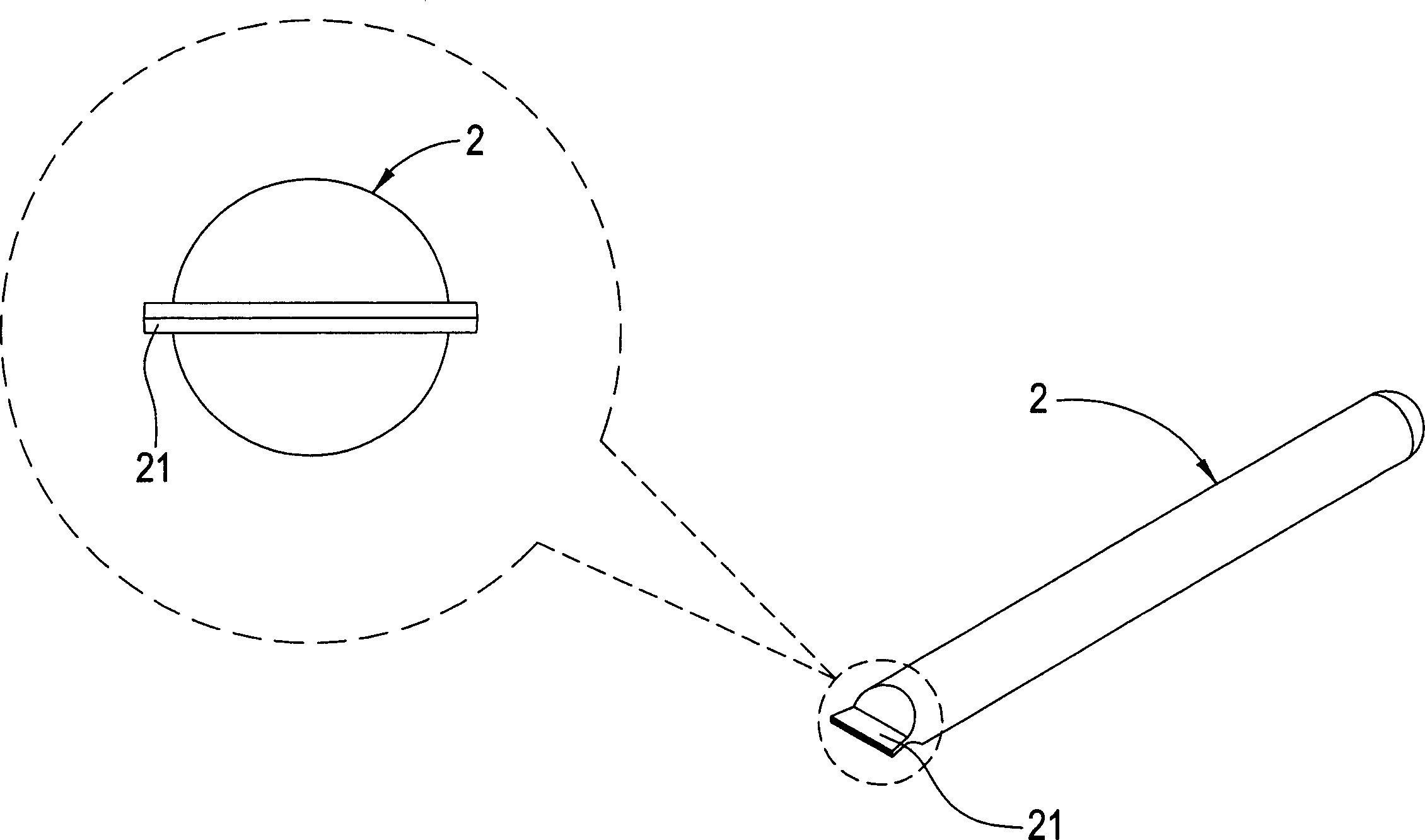
[0025] Step 1: If Figure 3A As shown, take the heat pipe 1 first, and turn a small section of the opening end of the heat pipe 1 into an extension section 11 with a smaller aperture, so that the diameter of the opening end is smaller than the diameter of the heat pipe 1, so as to facilitate heat conduction The addition of liquid and the extraction of air cause the heat pipe 1 to maintain a vacuum state, and through the small diameter of the extension section 11, it is difficult for air to enter the heat pipe 1 when the heat pipe 1 is sealed;

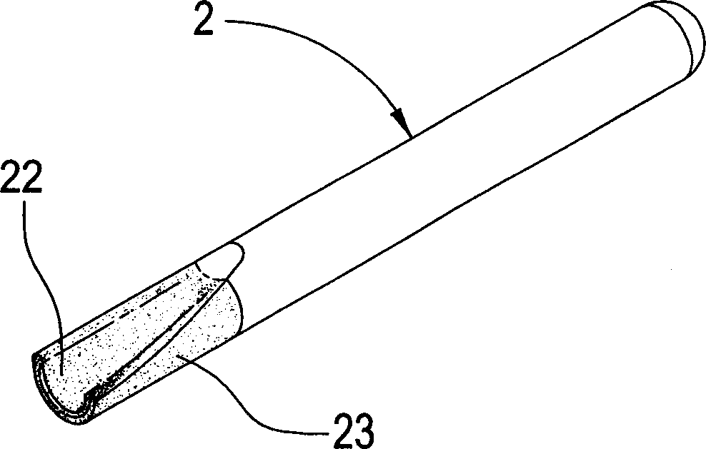
[0026] Step 2: If Figure 3B As shown, the extension section 11 of the heat pipe 1 is rotated and extruded through the mold, so that the tube wall of the extension section 1 is completely sealed by the continuous rotation and extrusion of the mold;

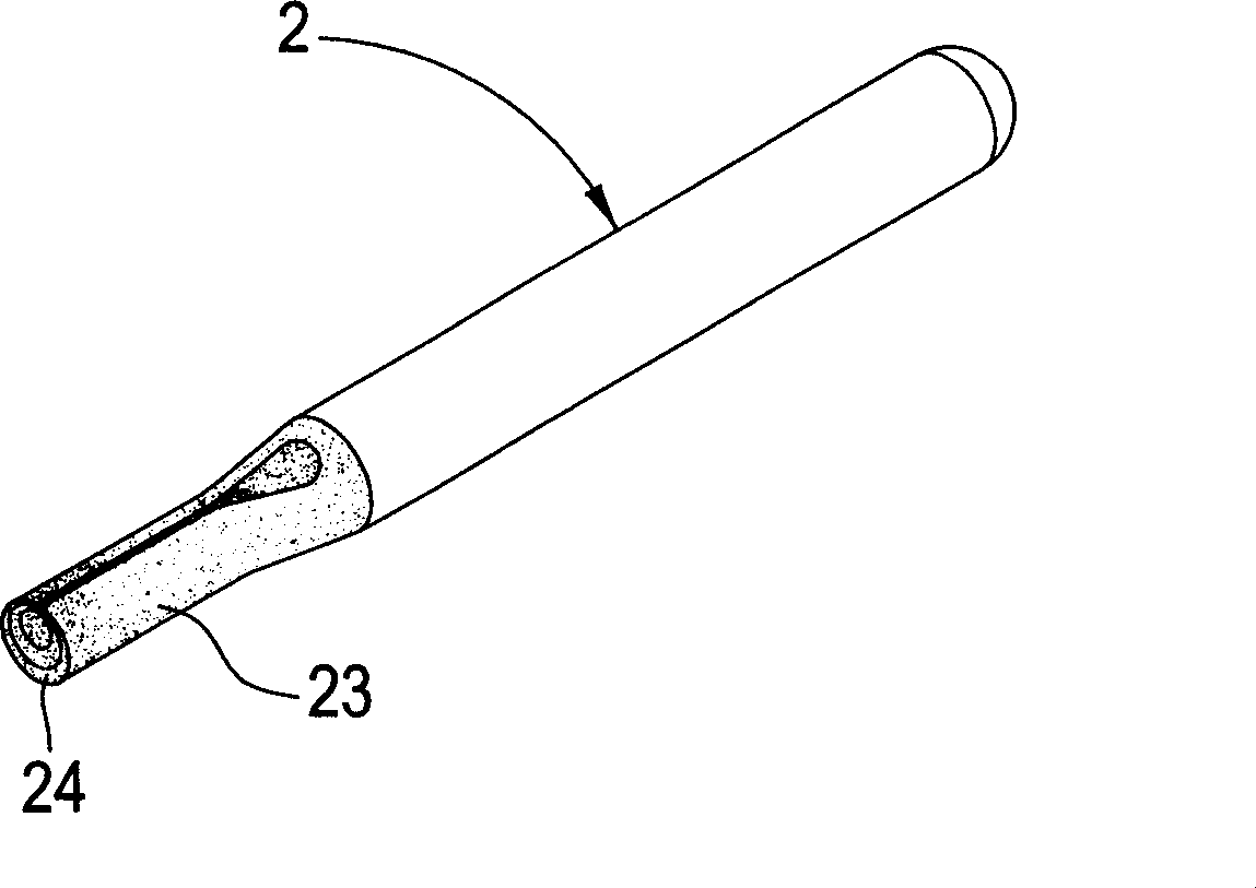
[0027] Step 3: If Fig...


PUM


Abstract

The invention discloses a closing method of heat pipe, which is characterized by the following: swinging the opening end of thermal conductive pipe into extension segment with small segment pipe diameter to add and extract air for thermal conductive liquid; spinning the extension segment through mould; closing the extension pipe wall through rotating and squeezing the mould; intercepting the sealing segment; welding the closure to prevent thermal conductive liquid from leaking.

Description

technical field [0001] The invention relates to a heat pipe sealing method. Background technique [0002] Existing heat pipes are slender pipes made of high thermal conductivity materials, and metal particles are attached to the inner wall to increase the heat conduction speed and increase the heat conductivity of the heat pipe. The air in the tube is sucked out to make the inside of the heat pipe into a vacuum state, and then both ends of the heat pipe are sealed, so that the best heat conduction effect can be achieved. [0003] The method of existing large heat pipe sealing is as figure 1 As shown, as shown in the figure, the opening end of the heat pipe 2 is pressurized by a machine to form a "one"-shaped flat seal 21, and then the flat seal 21 is cut off and welded on the truncated surface Sealing work; however, such a sealing method will cause the bonding strength and tightness of the sealing structure to be quite poor, so that the heat transfer fluid will easily flow...

Claims


Application Information

Patent Timeline
Patent Type & Authority Applications(China)
IPC IPC(8): B21D41/04
Inventor 管新宁
Owner THERMOKING TECH INT
Why Eureka
Try Eureka