Rotating mirror device with curved surface for laser scanner

A technology of laser scanners and curved mirrors, applied in optics, instruments, optical components, etc., can solve problems such as unevenness, weak sides, image distortion on the screen, etc., achieve uniform light intensity distribution, reduce difficulty, and uniform scanning speed Effect

Inactive Publication Date: 2006-07-19
HEBEI UNIV OF TECH
View PDF0 Cites 13 Cited by
  • Summary
  • Abstract
  • Description
  • Claims
  • Application Information

AI Technical Summary

Problems solved by technology

The laser scanner scanning method of the rotating mirror-galvanometer system has inherent geometric distortion of the scanning field of the plane mirror, which causes the spot on the galvanometer, that is, the non-linearity and non-time symmetry of the moving speed in the upward scanning direction of the plane screen, resulting in the image on the screen Distortion, light intensity distribution on the screen is strong in the middle, weak on both sides and uneven, etc.

Method used


Image

  • Rotating mirror device with curved surface for laser scanner
  • Rotating mirror device with curved surface for laser scanner

Examples


Embodiment Construction

[0016] In conjunction with the accompanying drawings, the specific description is as follows:

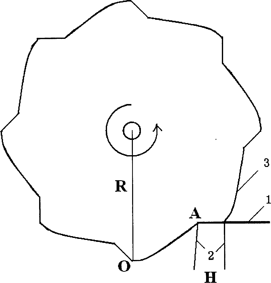
[0017] Such as figure 1 As shown, 1 incident beam, 2 reflected beam, 3 curved mirror.

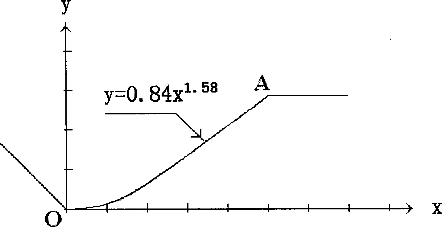
[0018] The angle between the incident beam and the normal of the reflected surface is 45 degrees, and the direction is from right to left. The angle between the reflected beam and the normal of the surface is also 45 degrees, and the direction is from top to bottom. The gear radius is set to unit 1, that is, R=1, thickness L=0.2 (unrestricted), number of teeth N=8, the distance from the incident beam direction to the center of rotation is 0.7071, and the angle formed by each curved mirror to the center of rotation is 36 degrees, the reflected light beam is translated between the gears by H=0.2. Establish a local coordinate system on a tooth, the coordinate origin is at the tooth tip, the y coordinate is along the opposite direction of the gear radius, and the x coordinate is along the vertical ...


PUM


Abstract

The invention relates to a laser scanner used curve rotating mirror which uses gear sharp to displace the regular polyhedron sharp and uses special curve reflector to displace the flat mirror of rotating mirror-oscillating mirror system to achieve the sense scan of the laser beam with even scan speed.

Description

technical field [0001] The invention relates to a curved surface rotating mirror device for a laser scanner, which uses a simple design scheme to realize unidirectional and nearly translational scanning of the light spot, and can be obtained in various laser scanner fields such as laser TV, laser on-line inspection and barcode recognition. widely used. Background technique [0002] Due to the characteristics of wide color gamut, high color saturation, flexible and variable screen size, easy to control, and no electromagnetic radiation, laser TV can be widely used in large-scale open-air image display, teaching demonstration, rear projection display equipment and other fields. Laser TV occupies a special position in the display field. Many countries in the world have plans to carry out research on laser TV, and great progress has been made. The scanning system produced by German Laser Display Technology Co., Ltd. writes images by fast scanning line by line in the entire disp...

Claims


Application Information

Patent Timeline
Patent Type & Authority Applications(China)
IPC IPC(8): G02B26/12G02B26/10H04N5/74
Inventor 范志新李志广
Owner HEBEI UNIV OF TECH
Why Eureka
Try Eureka