Deflection magnetic field type vacuum arc vapor deposition device

A deflecting magnetic field, vacuum arc technology, applied in the direction of vacuum evaporation coating, circuit, discharge tube, etc., can solve the problem of difficult to form compound film and so on

Inactive Publication Date: 2006-07-19
NISSIN ELECTRIC CO LTD
View PDF4 Cites 2 Cited by
  • Summary
  • Abstract
  • Description
  • Claims
  • Application Information

AI Technical Summary

Problems solved by technology

[0020] However if Image 6 As shown, when actually trying to form a compound film and a composite film with this device, the passage 950 of the ionized cathode material from an evaporation source 95 and the passage 960 of the ionized cathode material from another evaporation source 96 are due to the filter tank 93, The two deflection magnetic fields of 94 interact with each other, and sometimes instead of finally converging and heading towards the object s on the bracket, the two paths separate from each other in opposite directions, or separate after crossing each other, so it is difficult to form a desired compound film on the object s, etc.
When forming a film containing a base film and a film with other elements added, it is often difficult to finally concentrate each ionized cathode material toward the object on the bracket

Method used


Image

  • Deflection magnetic field type vacuum arc vapor deposition device
  • Deflection magnetic field type vacuum arc vapor deposition device
  • Deflection magnetic field type vacuum arc vapor deposition device

Examples


Embodiment Construction

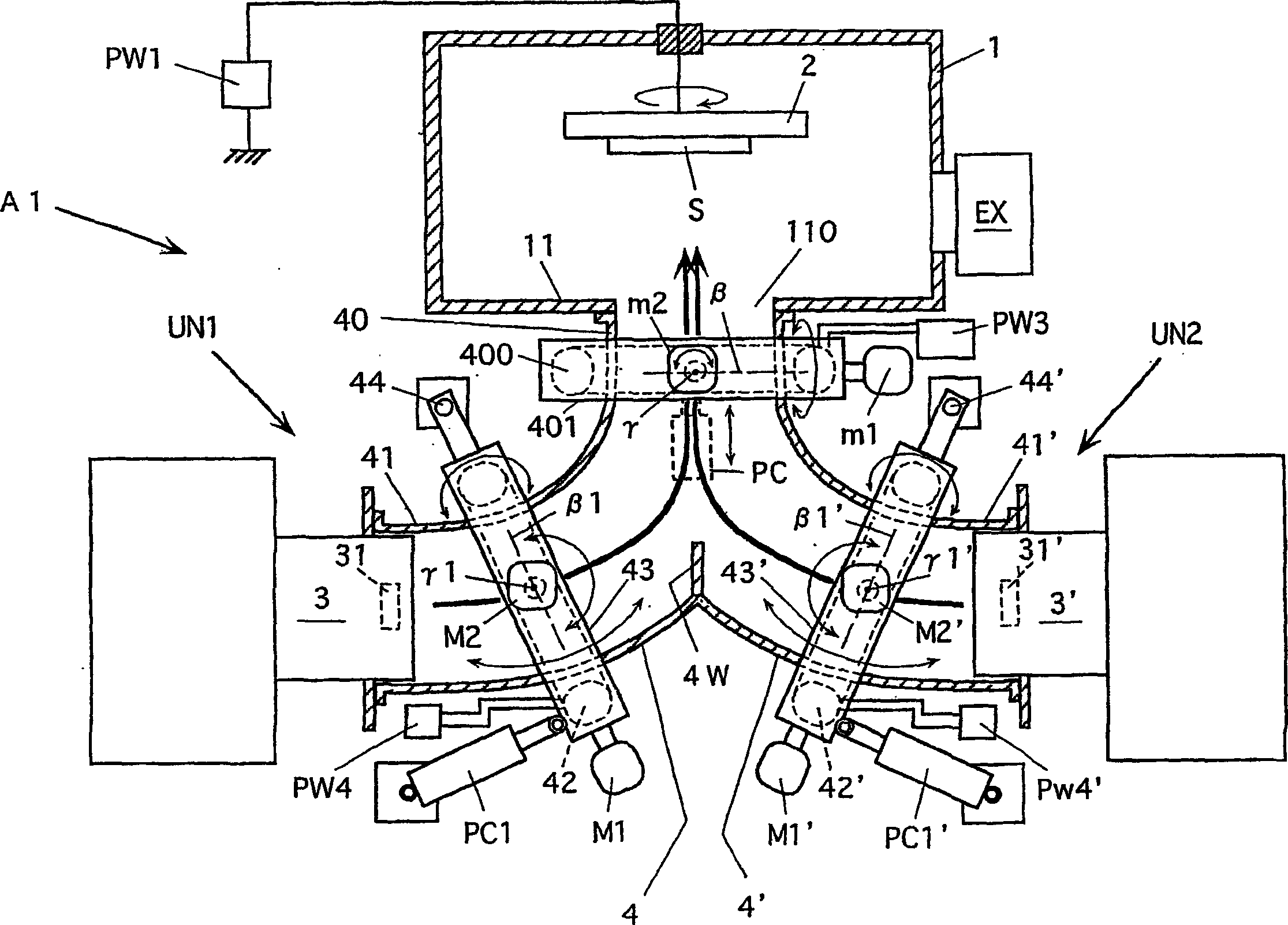
[0033] The deflection magnetic field type vacuum arc evaporation device of the present invention basically has a plurality of evaporation units, each of which includes an evaporation source that utilizes vacuum arc discharge between the anode and the cathode to evaporate and simultaneously ionize the cathode material, And the bending of one or more than two deflection magnetic field forming members that make the cathode material ionized by the evaporation source fly to the bracket so as to form a film containing the constituent elements of the cathode material on the film-formed part supported by the bracket lauter tank.

[0034] Then, the respective curved filter tanks of the plurality of evaporation units are formed such that the tank ends facing the bracket and the tank ends of other curved filter tanks facing the bracket are common tank ends, and At least one evaporation source is provided at opposite ends of the filter tank.

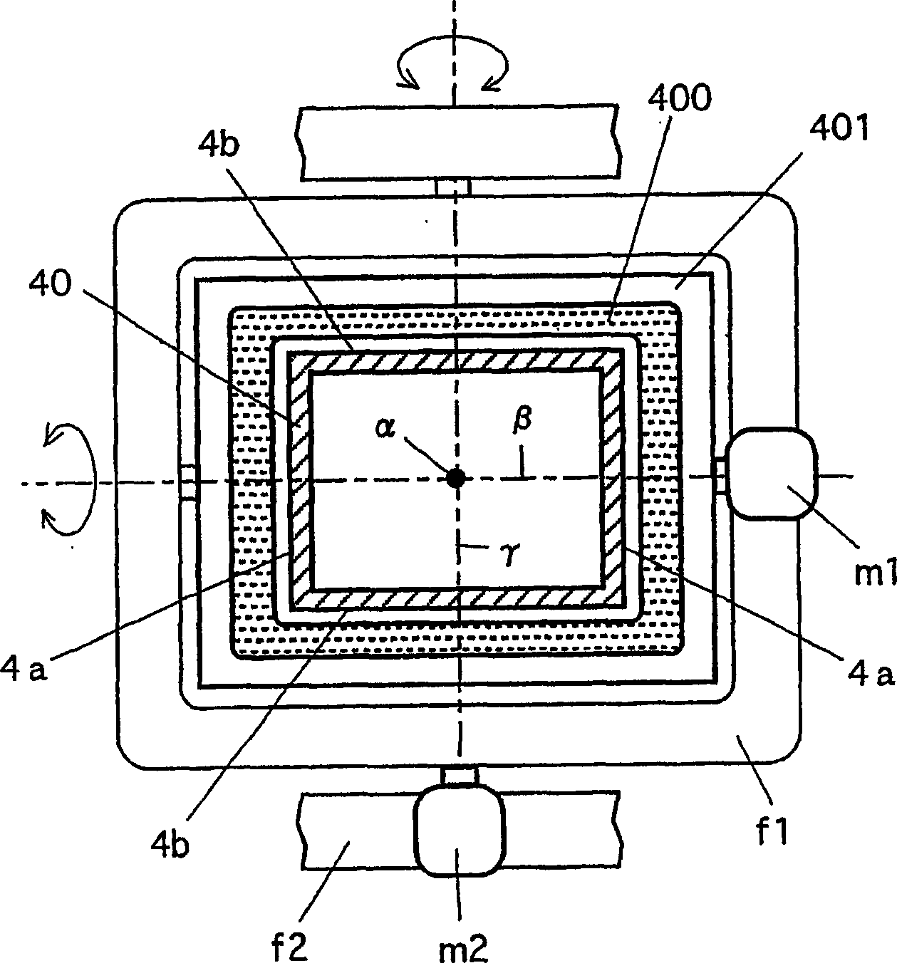
[0035] In addition, a magnetic field forming...


PUM


Abstract

A deflection magnetic field type vacuum arc vapor deposition device has vapor deposition units (UN1, UN2) and these units include evaporation sources (3, 3'), and curved filter ducts (4, 4') having magnetic field forming coils (400, 42, 42') annexed thereto. The ducts (4, 4') are formed with a common duct end (40) facing a film forming subject article support holder (2), and the vapor sources (3, 3') are installed on the opposite ends (41, 41') of the ducts. The common coil (400) is installed at the duct end (40), and another magnetic field forming coil (42, 42') is installed for each duct. Installation state adjusting device (motor (m1, m2), driving device (PC), motor (M1, M2), driving device (PC1), motor (M1', M2'), and driving device (PC1')) is installed for each coil. This vapor deposition device is capable of efficiently forming a high quality thin film of desired construction on the film forming subject article.

Description

technical field [0001] The present invention relates to a vacuum arc evaporation apparatus which can be used to form a thin film for improving at least one of wear resistance, sliding properties, corrosion resistance, etc., on objects such as automobile parts, machine parts, tools, molds, etc. . Background technique [0002] The vacuum arc evaporation device generates a vacuum arc discharge between the anode and the cathode in a reduced-pressure atmosphere, and uses this discharge to generate plasma containing a cathode material that evaporates and ionizes the cathode material, and causes the ionized cathode material to fly to the A film-forming member on which a thin film is formed. Generally, the part where a vacuum arc discharge is generated between the anode and the cathode and the arc discharge is used to ionize the cathode material is called an evaporation source or a vacuum arc evaporation source. Compared with plasma CVD (Chemical Vapor Deposition) apparatuses, vac...

Claims


Application Information

Patent Timeline
Patent Type & Authority Applications(China)
IPC IPC(8): C23C14/24C23C14/32H01J37/32
CPCH01J37/3266C23C14/325H01J37/32055C23C14/24C23C14/54C23C14/3464
Inventor 村上泰夫三上隆司
Owner NISSIN ELECTRIC CO LTD
Why Eureka
Try Eureka