Fluid cooling device

A fluid cooling and fluid technology, which is applied in fluid pressure actuators, oil supply tank devices, engine cooling, etc., can solve the problems of affecting the cooling capacity of heat exchangers and the loud operation of fluid cooling devices, so as to increase the possibility of modeling performance, save space, and improve suppression

Inactive Publication Date: 2011-08-17
HYDAC SYST
View PDF1 Cites 0 Cited by
  • Summary
  • Abstract
  • Description
  • Claims
  • Application Information

AI Technical Summary

Problems solved by technology

The thin-plate housing parts are also hardly suitable for suppressing the noise of the fan during operation, so that the running sound of the known fluid cooling device is loud
In addition, due to the thin-plate part construction of the housing parts, some sharp transitions and steps are produced in the ventilation channels, which adversely affect the free air flow in the region of the fan impeller due to turbulence, which in turn adversely affects the performance of the corresponding heat exchanger. cooling capacity

Method used


Image

  • Fluid cooling device
  • Fluid cooling device
  • Fluid cooling device

Examples


Embodiment Construction

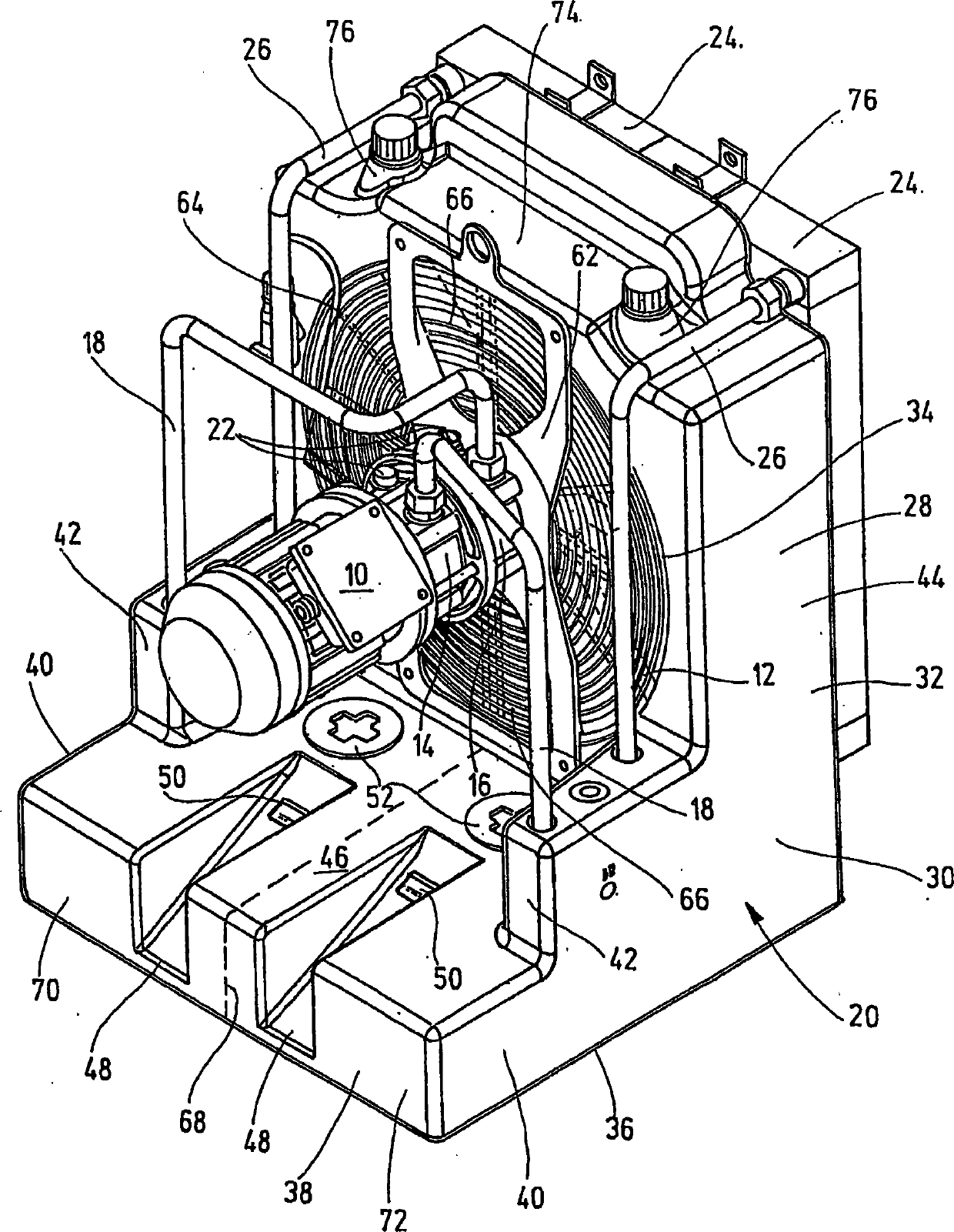
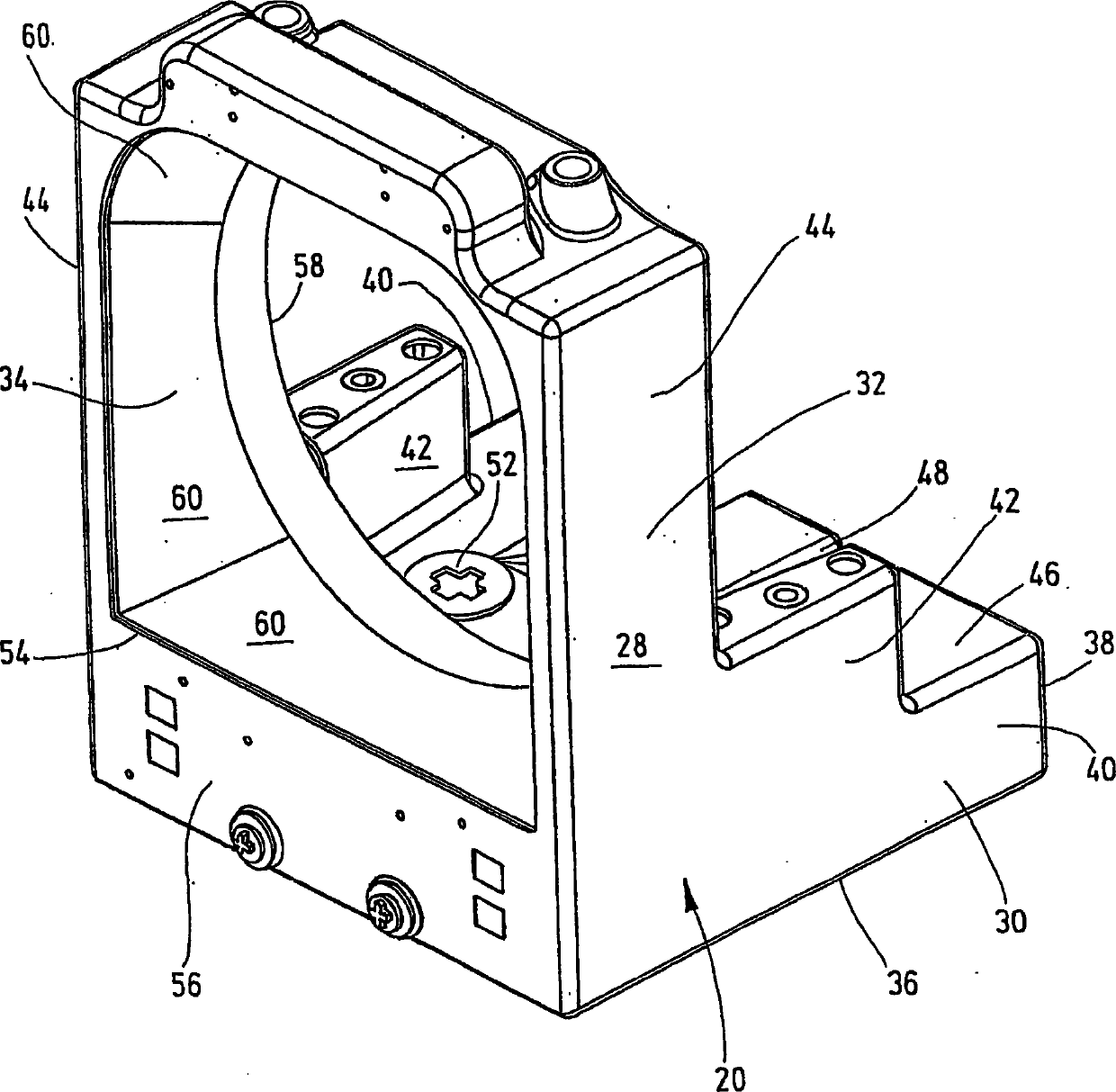
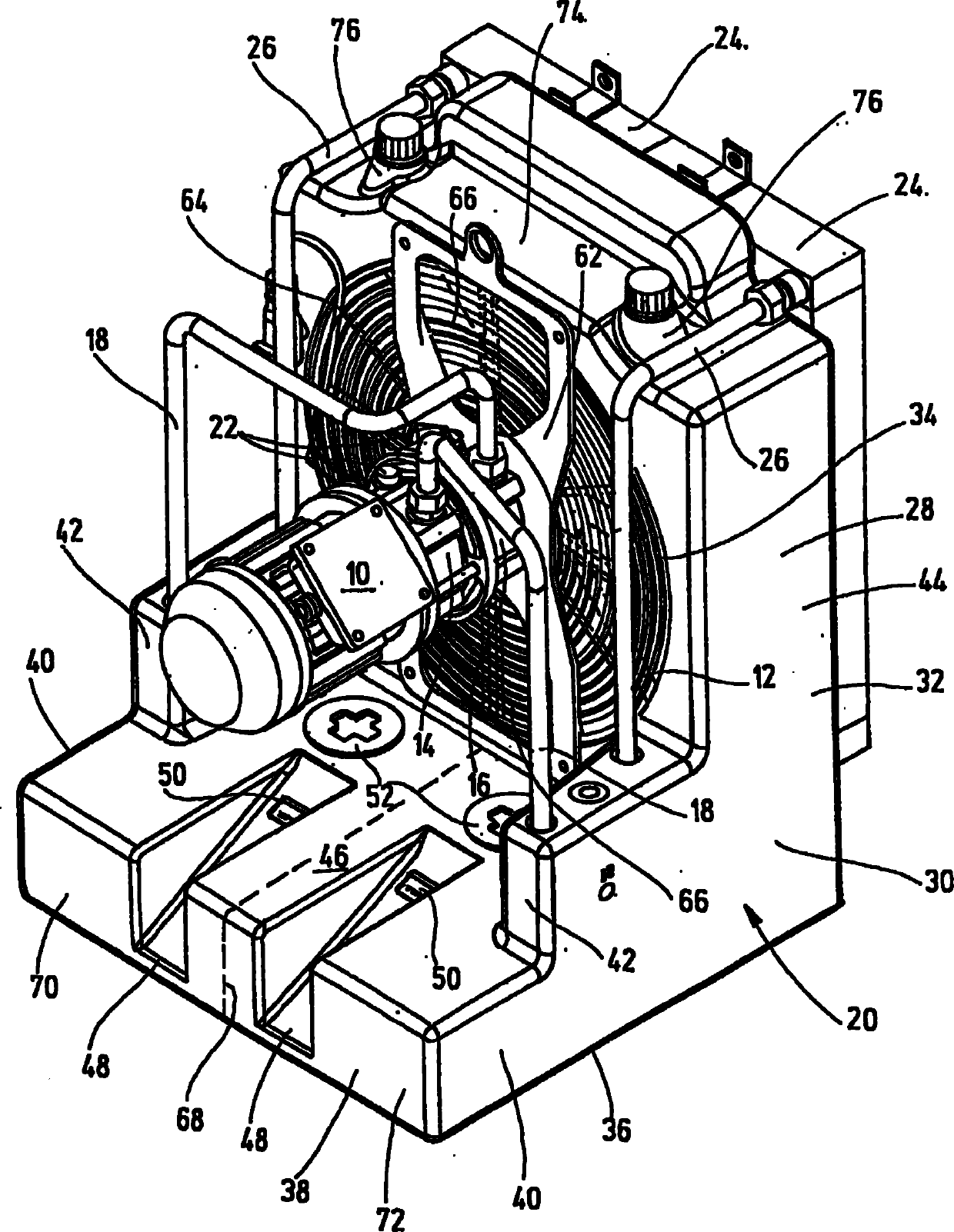
[0015] figure 1 The fluid cooling device of the present invention shown as a whole in , is designed as a modular component and can be sold as such. especially by figure 1 The fluid cooling device can be integrated into the existing hydraulic circuit of the engine or machine tool in order to achieve fluid cooling of the operating medium, for example in the form of hydraulic oil. according to figure 1 The view of the shows the normal installation position of the fluid cooling device, in which it can be installed vertically on a part of the workshop floor etc., but which can also be fixed to the machine and plant via a free side surface of the machine and plant part partly on.

[0016] The fluid cooling device has a general-purpose electric motor 10 , which drives a fan wheel 12 with individual fan wheel blades and two fluid pumps 14 , 16 . Each fluid pump 14 , 16 draws an assignable fluid, for example in the form of hydraulic oil, water-glycol, etc., from a reservoir general...


PUM


Abstract

The invention relates to a fluid cooling device in the form of a modular unit comprising a drive motor (10) which drives a ventilation wheel (12) which can be rotated in a ventilation housing (28). At least one fluid can be conveyed from a feed reservoir (20) into a hydraulic working circuit which, when in an operational state, basically heats the fluid and guides it to an associated heat exchanger (24), from which the cooled fluid returns to the feed reservoir (20). Parts of the feed reservoir (20) at least partially surround the ventilation wheel (12) and form the ventilation housing (28) which is preferably made of a plastic material, whereupon the ventilation housing is embodied as part of the feed reservoir, enabling the volume of the tank to be increased and resulting in increased damping of the noise of the ventilation wheel.

Description

technical field [0001] The invention relates to a flow cooling device comprising, as a combined component, a drive motor which drives a fan wheel rotatable in a fan housing, wherein at least one fluid can be supplied from a reservoir to a hydraulic working circuit, In operation it essentially heats the fluid and directs it to an associated heat exchanger from which cooled fluid is returned to the reservoir. Background technique [0002] A fluid cooling device of this type is known from EP 0 968 371 B1, the reservoir of which is formed in the form of a tank in the form of an oil tank and partially encloses the drive motor and the associated fluid in the form of a half shell with deep-drawn tank edges Pump. A housing part made of sheet metal is arranged between the deep-drawn groove edges of the reservoir, which accommodates the fan impeller and forms the air duct of a heat exchanger, through which the fluid is guided. In the known solution, a foot part is arranged below the...

Claims


Application Information

Patent Timeline
IPC IPC(8): F01P11/02F01P5/06F01P11/10F15B1/26F15B21/0423
CPCF15B21/042F01P11/10F15B1/26F01P11/029F01P5/06F15B21/0423
Inventor A·韦尔什
Owner HYDAC SYST
Why Eureka
Try Eureka