Controller for machine effecting end

一种控制器、机床的技术,应用在程序控制、金属加工、自动控制装置等方向,能够解决从动元件和机床加工端位移大等问题

Inactive Publication Date: 2006-07-26
FANUC LTD
View PDF3 Cites 18 Cited by
  • Summary
  • Abstract
  • Description
  • Claims
  • Application Information

AI Technical Summary

Problems solved by technology

[0008] However, in the case of low machine stiffness between the driven element and the machine end, the movement of the driven element relative to the machine end does not always coincide with the commanded movement
Moreover, in the case of a machine tool that is required to perform high-speed, high-precision machining at high acceleration, even if the machine tool has high rigidity, the displacement between the driven element and the machining end of the machine tool due to torque etc. sometimes becomes so large that it cannot neglect

Method used


Image

  • Controller for machine effecting end
  • Controller for machine effecting end
  • Controller for machine effecting end

Examples


Embodiment Construction

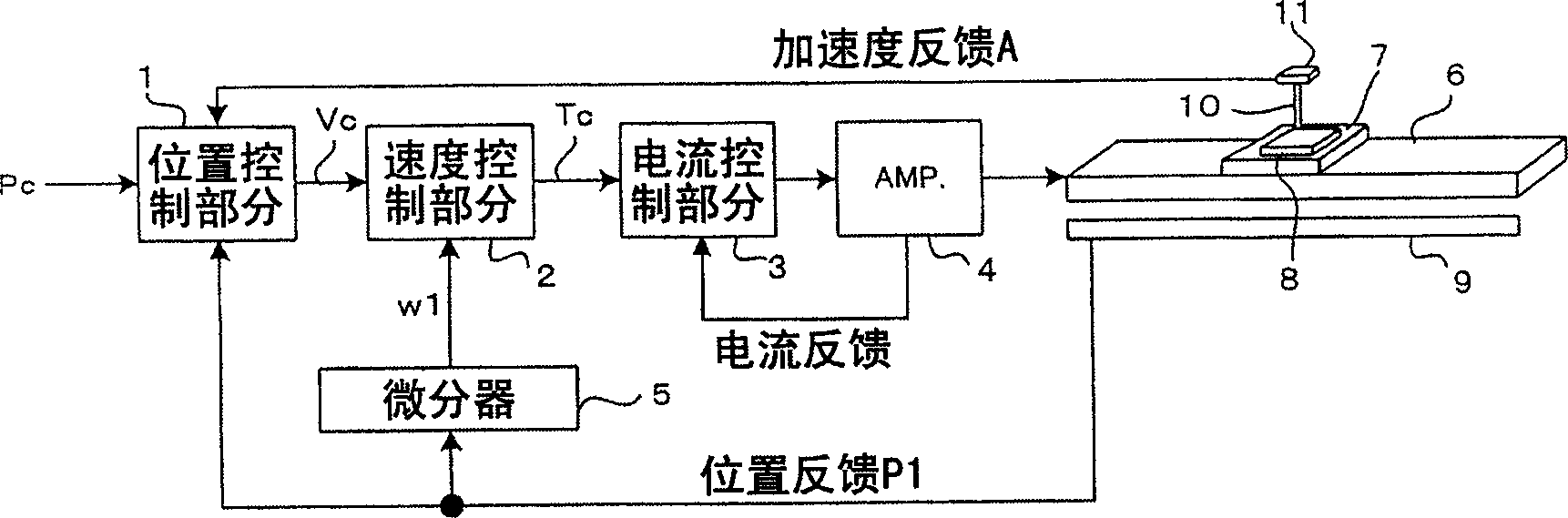
[0023] figure 1 It is a block diagram showing the main part of the first embodiment of the present invention. In the first embodiment, the acceleration sensor is mounted to a part at the machining end of the machine tool where a tool or the like actually arranged to be in contact with a workpiece to be machined is fixed. Based on the acceleration detected by the acceleration sensor, the displacement of the part holding the tool is obtained and corrected so that the tool can move as commanded.

[0024] In the described embodiment, by way of example, a linear motor is used as a servo motor for driving the driven element. exist figure 1 , the workpiece 8 to be machined is connected to a driven element 7 driven by a linear motor 6 . The acceleration sensor 11 is connected to a component 10, which is the machining end of the machine tool, to which is fixed a tool, such as a tool for performing machining on a workpiece. The relative position of the workpiece 8 (driven element 7 ...


PUM


Abstract

The present invention provides a controller for controlling a position of a driven element with respect to a machine effecting end so as to be in accord with a command. An acceleration sensor is mounted to a member of the machine effecting end to which a tool is attached. Acceleration detected by the sensor is subjected to second-order integration by a torsion estimator to obtain displacement Deltatheta of the machine effecting end from the original position. Position feedback P 1 of a driven element is subtracted from position command Pc to obtain first position deviation epsilon1. The displacement Deltatheta is added to the first position deviation epsilon1 to obtain second position deviation epsilon2. The second position deviation epsilon2 is subjected to learning control of a learning controller to obtain a correction value, which is added to the first position deviation epsilon1 to obtain velocity command Vc. The second position deviation is the sum of the displacement epsilon1 of the driven element from the commanded position and the displacement Deltatheta of the machine effecting end relative to the driven element, and thus signifies a positional displacement of the machine effecting end from the commanded position. The second position deviation is subjected to the learning control so as to converge to ''0'', whereby the position of the driven element with respect to the machine effecting end becomes in accord with the command.

Description

technical field [0001] The present invention relates to controllers for controlling machine tools, and more particularly, to the control of the position of a driven element relative to the machining end of a machine tool. Background technique [0002] In machine tools, in order to control the position and speed of a driven element driven by a servo motor, position feedback control, speed feedback control, and current feedback control are generally performed so that the position and speed of the driven element can match the commanded position and speed. [0003] Even when such position, speed and current feedback control is performed, the driven element tends to vibrate when the acceleration of the servo motor changes suddenly. In order to avoid this, a control method has been proposed in which an acceleration sensor for detecting the acceleration of the driven element is provided, the signal output from the acceleration sensor is subtracted from the current command obtained ...

Claims


Application Information

Patent Timeline
Patent Type & Authority Applications(China)
IPC IPC(8): B23Q15/20B23Q15/22G05D3/12
CPCG05B19/404
Inventor 岩下平辅丰泽雪雄园田直人
Owner FANUC LTD
Why Eureka
Try Eureka