Eureka AIR delivers breakthrough ideas for toughest innovation challenges, trusted by R&D personnel around the world.

Method and apparatus for converting conservative internal force into non-conservative internal force

An internal force, conservative technique applied to mechanisms, engines, machines/engines, etc. that generate mechanical power

Inactive Publication Date: 2006-07-26
罗耀文
View PDF1 Cites 2 Cited by
  • Summary
  • Abstract
  • Description
  • Claims
  • Application Information

AI Technical Summary

Problems solved by technology

my country's patent application 200510018138 discloses a device that uses the weight of objects to drive mechanical rotation. Although the structural design is ingenious, there is no fundamental reason for clarifying and solving the problem from the theory of mechanical energy conservation.

Method used


Image

  • Method and apparatus for converting conservative internal force into non-conservative internal force
  • Method and apparatus for converting conservative internal force into non-conservative internal force
  • Method and apparatus for converting conservative internal force into non-conservative internal force

Examples


Embodiment 1

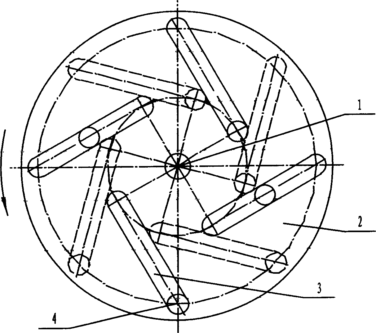
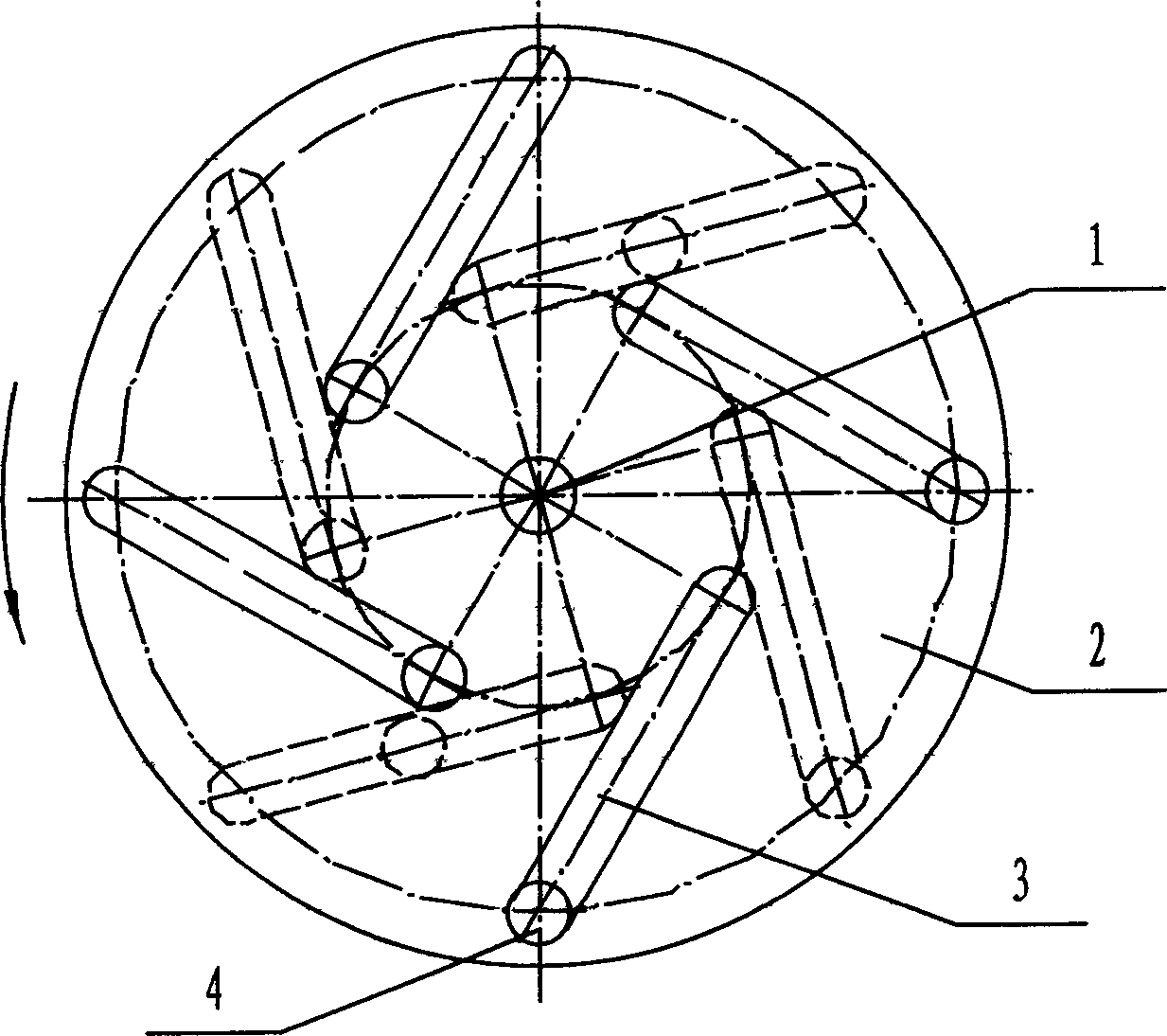
[0033] The diameter of the disc-shaped body is 3000 mm, and there are 8 grooves arranged alternately on the front and back sides, evenly distributed, and inclined at 30°, of which 4 are on each side. In order to reduce the moment of inertia of the disc-shaped body, it adopts an aluminum alloy frame structure; Body is cylinder, total number n=8, adopts steel, and diameter is 200 millimeters, and length is 280 millimeters, and the quality m=69kg of cylinder; The diameter of the circle where the inner end of the groove is located is 2r=1340 mm; the structural form is as image 3 shown.

Embodiment 2

[0035] The diameter of the disc-shaped body is 9500 mm, and there are 8 grooves arranged alternately on the front and back sides, evenly distributed, and inclined at 45°, of which 4 are on each side. In order to reduce the moment of inertia of the disc-shaped body, it adopts a steel frame structure; The total number of spheres is n=8, made of steel, with a diameter of 600 mm, and the mass of rolling spheres is m=887.8kg; the diameter of the circle where the sphere is located at the outer end of the groove is 2R=8202 mm, and the diameter of the circle where the sphere is located at the inner end of the groove is 2r=5800 mm; structural form such as image 3 shown.

Embodiment 3

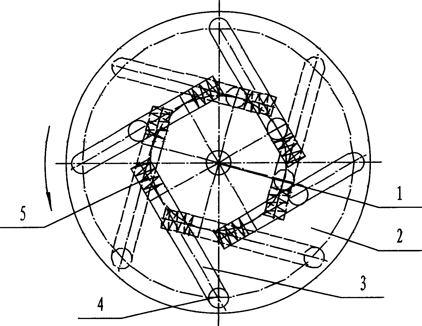
[0037] The diameter of the disc-shaped body is 9500 mm, and there are 12 grooves arranged alternately on the front and back sides, evenly distributed, and inclined at 30°, of which 6 are on each side. In order to reduce the moment of inertia of the disc-shaped body, it adopts a steel frame structure; Body is cylinder, total number n=12, adopts steel, and diameter is 600 millimeters, and length is 720 millimeters, and the quality m=1598kg of cylinder; The diameter of the circle where the inner end of the groove is located is 2r=4100 mm; the structural form is as Figure 4 shown.


PUM


Abstract

The invention relates to a method for changing the conservative internal force as gravity into non-conservative internal force, and relative device. It can solve the problem that the conservative internal force can not make power. Based on the Newton theory, the mechanical energy conservation theory, and the law of conservation of momentum, via mechanical energy storage, transmission, inverse releasing and layering, it changes the conservative internal force into the non-conservative internal force which can make power. Wherein, the inventive device, is a disc element (2) rotating around a axle (1), whose two surfaces have several uniformly distributed grooves (3) which are inclined from inner to outer (or from outer to inner) and from upper to lower; and each groove comprises a ball (or cylinder) (4) which can roll freely; and one end of each groove has a kinetic energy storing device (5) formed by a spring, a piston and a stop pin. The invention can be used to drive the machine with lower rotational speed and drive the generator.

Description

technical field [0001] The invention relates to a method and a dynamic mechanical device for changing gravity, the conservative internal force, into a non-conservative internal force. Background technique [0002] In modern technology, there are many kinds of power machinery, such as: steam engine, steam turbine, gas turbine, gasoline engine, diesel engine, jet engine, etc. Although these machines occupy a dominant position in the field of power machinery, their Operation will consume a certain amount of non-renewable energy, such as: coal, oil, natural gas, and so on. Among the power machinery using renewable energy, water turbines, windmills, and equipment that use solar energy to obtain heat and electricity, etc., although these technologies and equipment are relatively mature, their use is subject to certain restrictions. That is, the corresponding machines and equipment can only be used in places with abundant water resources, wind resources or sufficient sunlight. my...

Claims


Application Information

Patent Timeline
IPC IPC(8): F03G3/00F03G7/10
Inventor 罗耀文
Owner 罗耀文
Why Eureka
Eureka Blog
Learn More