Dynamic reactive compensation control method

A control method and compensation control technology, applied in the field of dynamic reactive power compensation control, can solve problems such as difficulty in ensuring the accuracy of dynamic reactive power compensation

Active Publication Date: 2006-07-26
顺特电气设备有限公司
View PDF0 Cites 18 Cited by
  • Summary
  • Abstract
  • Description
  • Claims
  • Application Information

AI Technical Summary

Problems solved by technology

[0005] These load compensation algorithms have their own characteristics and have their own application fields, but they all belong to open-loop control, or called feed-forward control, and it is difficult to guarantee the accuracy of dynamic reactive power compensation in practical applications.

Method used


Image

  • Dynamic reactive compensation control method
  • Dynamic reactive compensation control method
  • Dynamic reactive compensation control method

Examples


Embodiment Construction

[0090] The present invention will be further described below in conjunction with the accompanying drawings and embodiments.

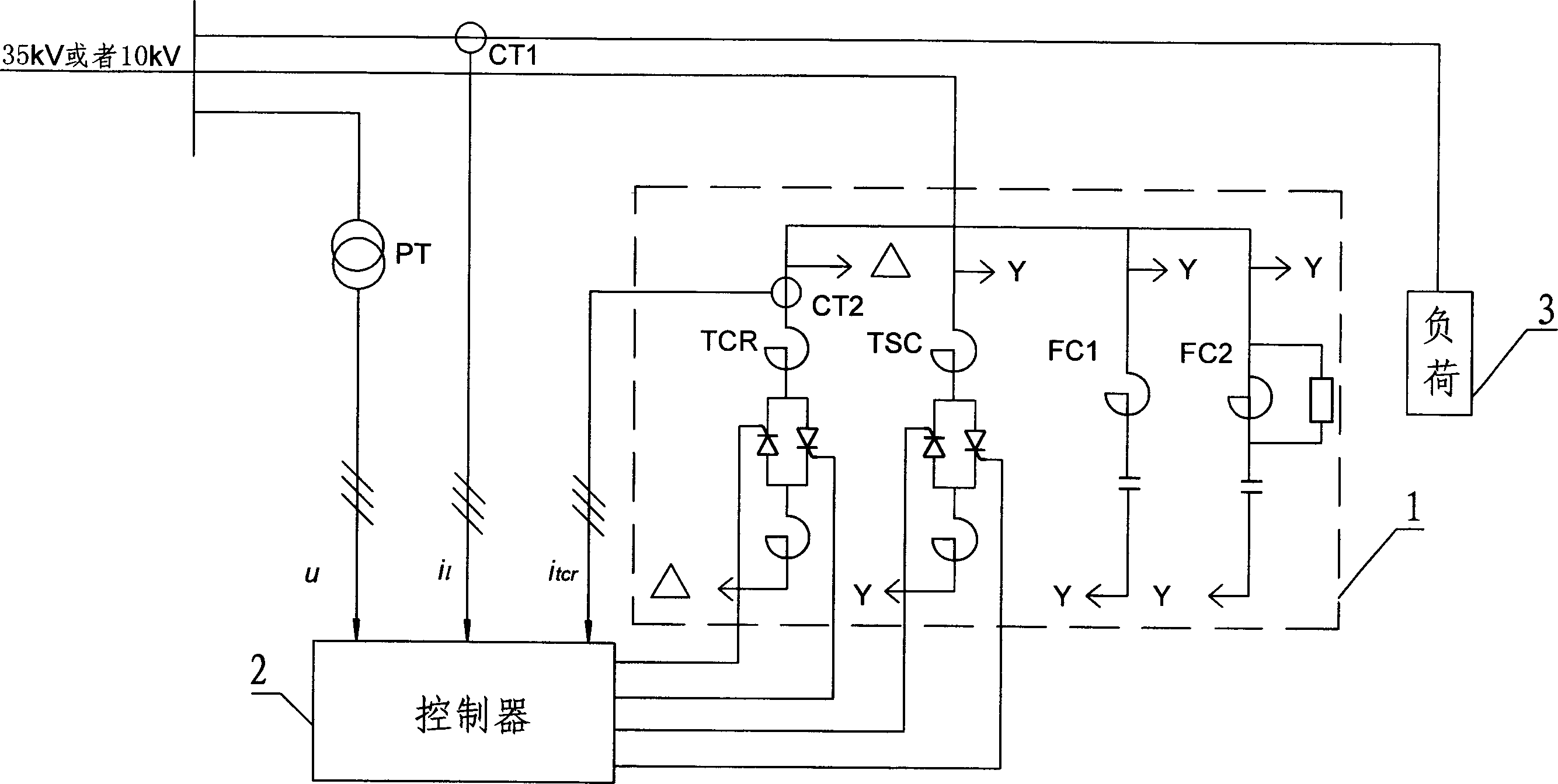
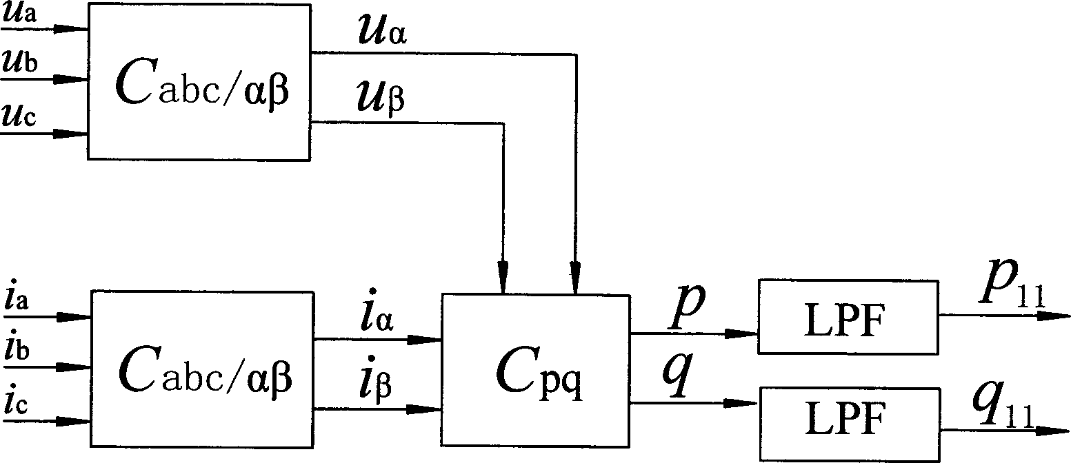
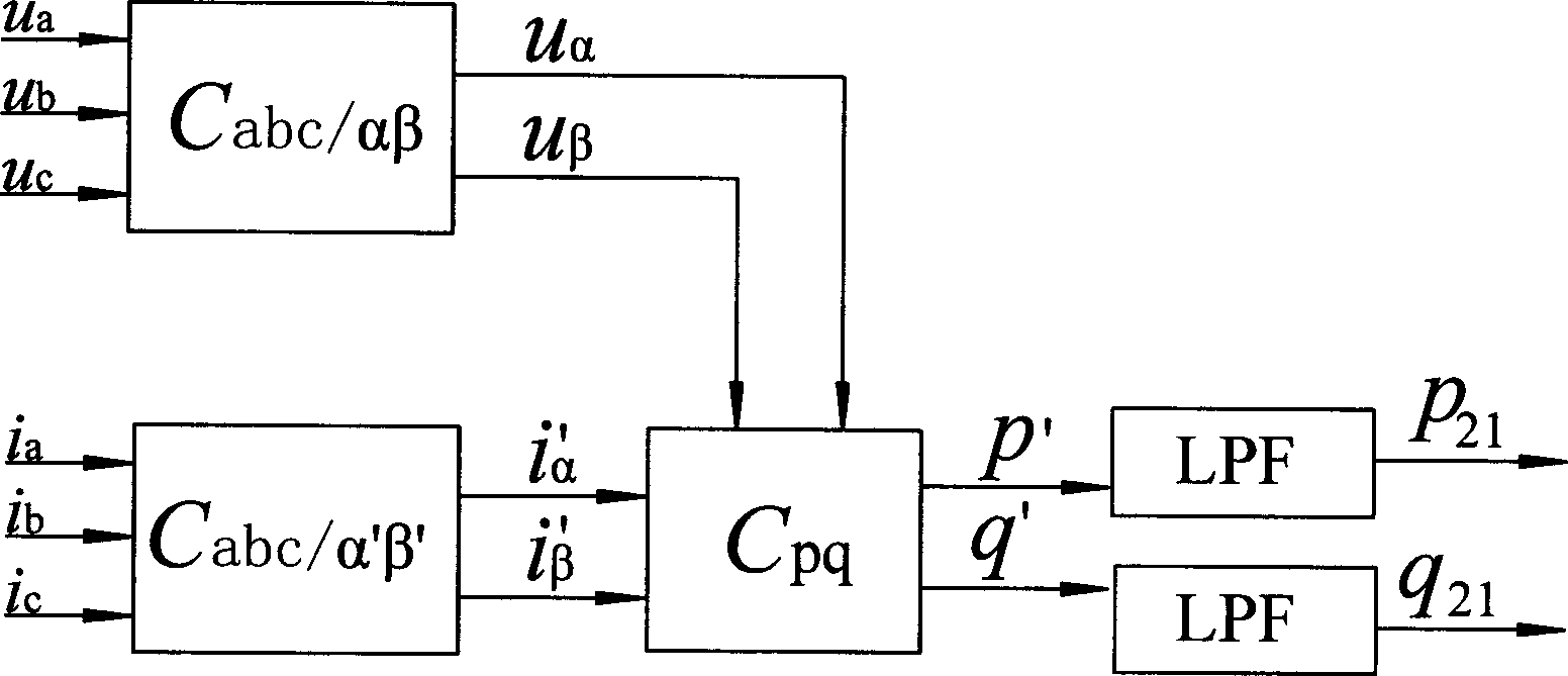
[0091] see figure 1 and Figure 4 , the present invention provides a dynamic reactive power compensation control method, the control method is connected in parallel with a static dynamic reactive power compensation device (SVC) in the distribution network, and then detects that the static dynamic reactive power compensation device is connected in real time The system voltage, load current, and current signal of the thyristor-controlled separate reactor (TCR) can be calculated in real time, and the susceptance value of each phase of the static dynamic reactive power compensation device should be compensated, so as to realize the control of the thyristor-controlled separate reactor ( Thyristor firing angle in TCR) and thyristor switching control in parallel thyristor switched capacitor (TSC); see figure 1 , The static dynamic reactive power compensation...


PUM


Abstract

This invention relates to one dynamic powerless compensation method, which comprises the following steps: connecting one static powerless compensation device in the distribution network; then real time testing the static dynamic powerless compensation device joint voltage, load current, thyristor control separation resistance current signals; computing out static dynamic powerless compensation device each relative capacity value to realize the control to the trigger angle in the thyristor separation resistance and paralleled thyristor breaking control.

Description

technical field [0001] The invention relates to a dynamic reactive power compensation control method. Background technique [0002] With the continuous growth of my country's economy, the power load has increased rapidly, and the user's reactive power demand has also increased significantly. This has brought more serious problems to my country's power grid, which is already short of power. Therefore, the role of the static dynamic reactive power compensation device is appear increasingly prominent. [0003] The main objectives of the industrial static dynamic var compensation device (Static Var Compensator, hereinafter referred to as SVC) mainly include three aspects: suppressing voltage fluctuation and flicker caused by disturbance load changes; compensating the reactive current required by the load and improving the power factor ; Compensation for unbalanced active and reactive loads. The two most basic requirements of industrial SVC are rapidity and phase-splitting compe...

Claims


Application Information

Patent Timeline
Patent Type & Authority Applications(China)
IPC IPC(8): H02J3/18G05F1/70
CPCY02E40/30
Inventor 傅闯卢志良徐德鸿刘燕
Owner 顺特电气设备有限公司
Why Eureka
Try Eureka