Technological process of making wing type centrifugal vane whell

A manufacturing process, centrifugal impeller technology, applied in non-variable pumps, pump elements, components of pumping devices for elastic fluids, etc., can solve the problems of reduced space, large investment, and increased difficulty

Inactive Publication Date: 2006-08-02
SHANDONG UNIV
View PDF0 Cites 14 Cited by
  • Summary
  • Abstract
  • Description
  • Claims
  • Application Information

AI Technical Summary

Problems solved by technology

The traditional airfoil-shaped hollow blades are rolled with thin iron plates, and then the blades are welded to the front and rear discs. The manufacturing process is complicated, the investment in molds, process equipment, and special equipment is large, the man-hours and manufacturing costs are high, and the shape of the impeller is accurate. , poor appearance quality
Recently, foreign advanced enterprises manufacture blades with hollow wing section aluminum profiles, and then weld the blades with the front and rear discs. This manufacturing method reduces the man-hour cost and manufacturing cost, and improves the aerodynamic, noise performance and appearance quality of the fan. However, Still can not get rid of the limitations of the welding process - as the number of blades increases or the diameter of the impeller decreases, the space between two adjacent blades decreases, the difficulty of welding process and welding joint grinding increases or even manual operation is impossible

Method used


Image

  • Technological process of making wing type centrifugal vane whell
  • Technological process of making wing type centrifugal vane whell
  • Technological process of making wing type centrifugal vane whell

Examples


Embodiment

[0023] Embodiment: it comprises following processing step

[0024] A. Manufacture of Airfoil Blades

[0025] a. Outsourcing processing of hollow aluminum profiles with non-equal wall thickness and wing section with longitudinal ribs, in which the ratio of the thicker curved surface wall thickness to the thinner plane wall thickness is greater than 2, and the ratio of the longitudinal rib wall thickness to the thinner wall thickness is greater than 3 ;

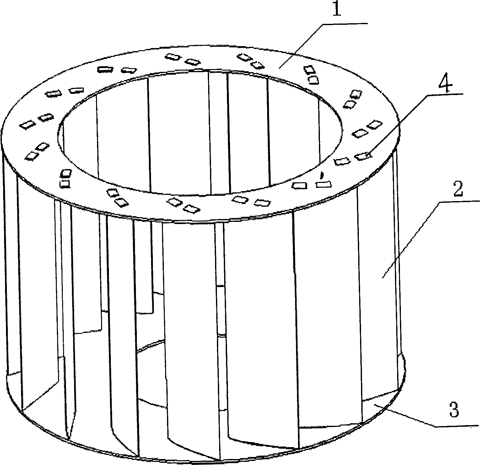
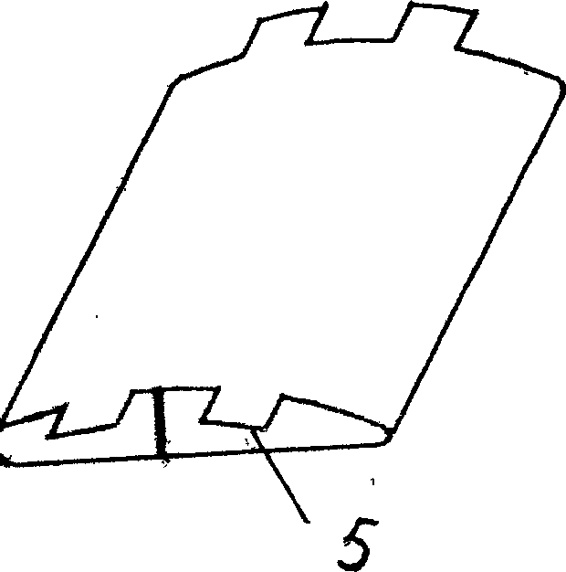
[0026] b. If figure 2 , image 3 , Figure 4 , Figure 5 and Figure 6 As shown, the protrusion of the blade end on the joint surface of the punched blade end and the straight front disk 1, the straight rear disk 3 or the blade end and the arc or tapered front disk 1 and the straight rear disk 3 Platform 5, the mold should have the functions of shearing and indentation, wherein when punching the boss 5 of the blade end on the joint surface of the blade end and the arc-shaped or conical front disk 1, and the straight rear...


PUM


Abstract

The technological process of making wing type centrifugal vane wheel includes the steps of: making the profile with single layer of boss and planar, arc or conic surface in ribbed hollow aluminum section bar with unequal wall thickness and wing, forming slots on the flat front and back disc and arc or conic front disc, inserting, bending and connecting to form vane wheel. The technological process has no welding and no limitation in vane number, and the produced vane wheel has high efficiency, low noise, small size and low cost.

Description

technical field [0001] The invention relates to a method for manufacturing an impeller, in particular to a method for manufacturing an airfoil centrifugal impeller. Background technique [0002] We know that airfoil centrifugal fans are famous for their high efficiency and low noise. The traditional airfoil-shaped hollow blades are rolled with thin iron plates, and then the blades are welded to the front and rear discs. The manufacturing process is complicated, the investment in molds, process equipment, and special equipment is large, the man-hours and manufacturing costs are high, and the shape of the impeller is accurate. , The appearance quality is poor. Recently, foreign advanced enterprises manufacture blades with hollow wing section aluminum profiles, and then weld the blades with the front and rear discs. This manufacturing method reduces the man-hour cost and manufacturing cost, and improves the aerodynamic, noise performance and appearance quality of the fan. Howe...

Claims


Application Information

Patent Timeline
Patent Type & Authority Applications(China)
IPC IPC(8): F04D29/30F04D29/62
Inventor 左文泉田新诚李贻斌荣学文徐青宋锐张东亮周风余马昕彭勃
Owner SHANDONG UNIV
Why Eureka
Try Eureka