
Size variable touch system based on pattern recognition

An image recognition and variable technology, applied in the input/output process of data processing, instruments, electrical and digital data processing, etc., can solve the problems of cumbersome, large-scale resistive screen, easy to be exposed to sunlight, etc., to simplify the hardware circuit , convenient design and application, low-cost effect

Inactive Publication Date: 2006-08-02
邢休东 +1
View PDF4 Cites 11 Cited by
  • Summary
  • Abstract
  • Description
  • Claims
  • Application Information

AI Technical Summary

Problems solved by technology

[0007] The above types of touch screens have their limitations, and they have the following disadvantages: 1. The conductive film of the resistive touch screen is easily damaged and has poor anti-violence performance, so it is not suitable for use in public places; 2. Surface dirt such as water and dust will absorb sound. Surface wave and surface acoustic wave touch screens have high environmental requirements, cannot be used outdoors, and need to be cleaned regularly; 3. Infrared touch screens require more electronic components, have low resolution, and are susceptible to interference from sunlight, etc., reliable 4. The stability of capacitive touch screen is poor, and drift phenomenon will occur
5. Due to the technical defects of the existing touch screens, the existing touch screens have obstacles in the production of large-size touch screens. For example, the large size of the resistive screen is affected by the processing characteristics of the conductive film; and the surface acoustic wave Due to the attenuation of the sound wave on the glass surface, the large-size acoustic wave touch screen cannot meet the needs of the market; the resolution of the infrared screen cannot meet the user's requirements.
Since the main DSP has to complete a series of tasks such as image data reception, pointer identification, pointer position calculation and interactive communication with the main computer, it requires the use of high-end DSP and complex control circuits, which increases the cost of the touch system; At the same time, the triangulation method used to determine the position has a large amount of calculation and is relatively cumbersome, which is not conducive to the change of the size of the touch system.

Method used


Image

  • Size variable touch system based on pattern recognition
  • Size variable touch system based on pattern recognition
  • Size variable touch system based on pattern recognition

Examples


Embodiment 1

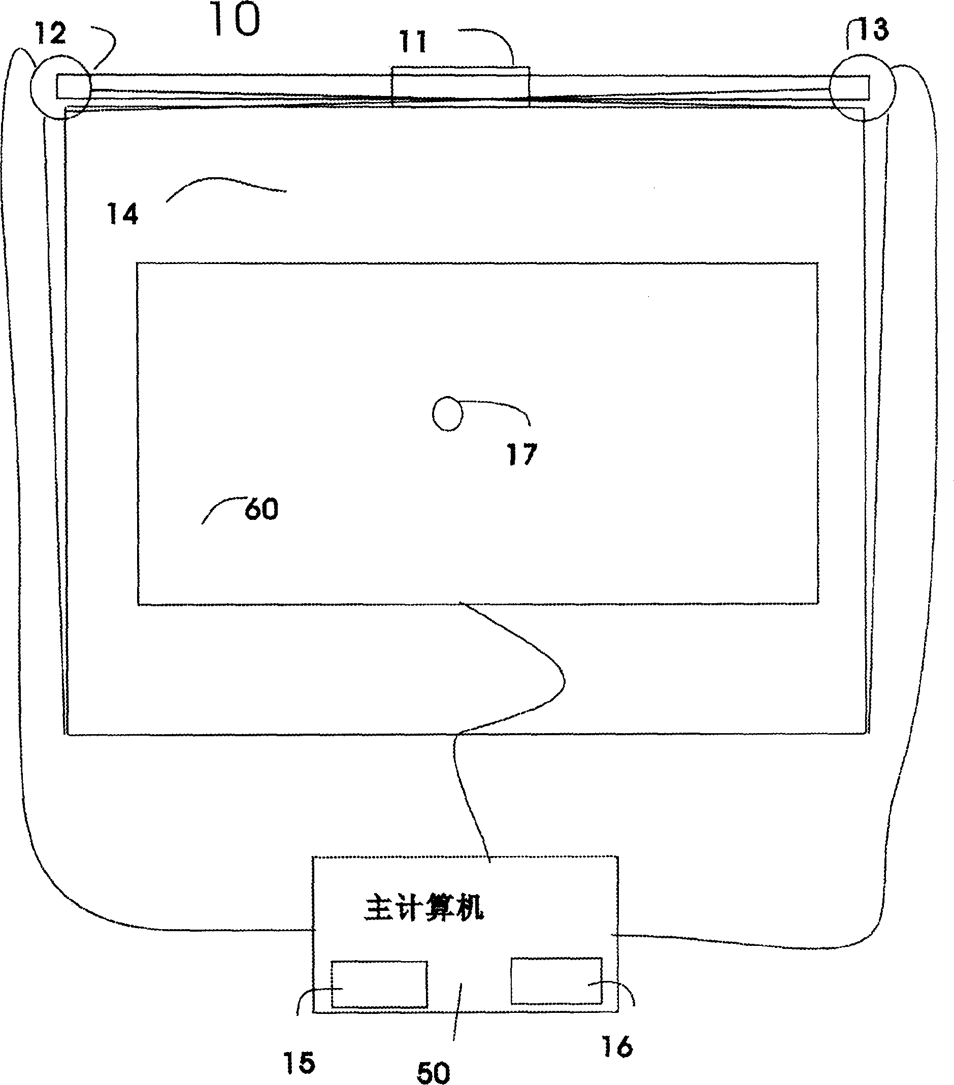
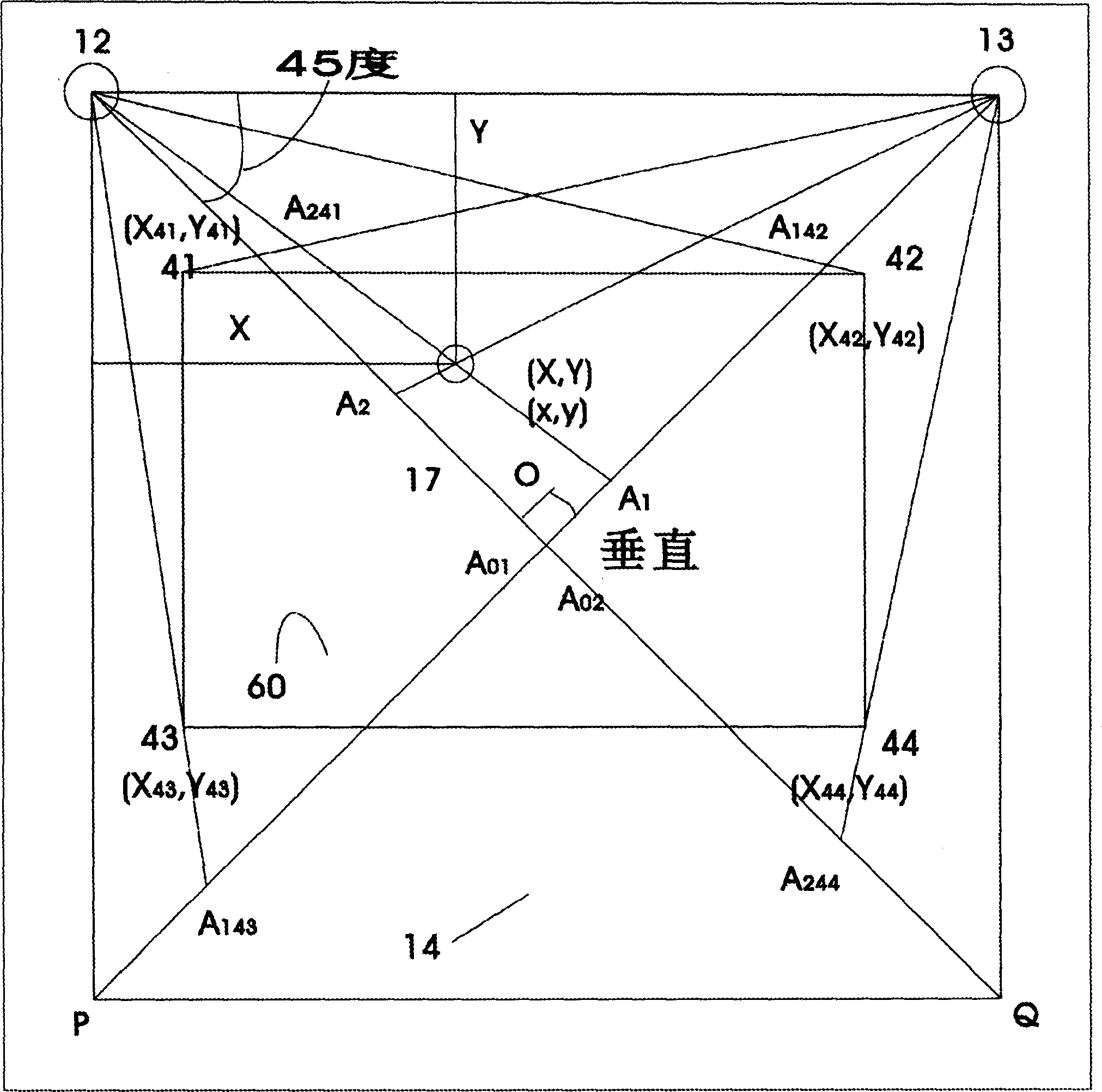
[0025] attached figure 1 The variable-size touch system based on image recognition of the present invention is shown, which is indicated by reference numeral 10 in the drawings. As shown in the figure, the touch system 10 includes a rod body 11 of variable length, two cameras 12, 13 are installed at both ends of the rod body, and the cameras are respectively connected to a computer 50 through a high-speed serial data bus such as USB or 1394. , install and run the driver program 15 for image recognition and position calculation included in the touch system 10 and the corresponding auxiliary program 16; the viewing areas of the cameras 12 and 13 overlap each other to form a rectangular section with the two cameras as adjacent vertices 14, the interval 14 covers the display interval of the display device 60; generally, the display interval of the display device 60 is the touch interval for the user to operate; When operating in the display section, the computer will hand over th...

Embodiment 2

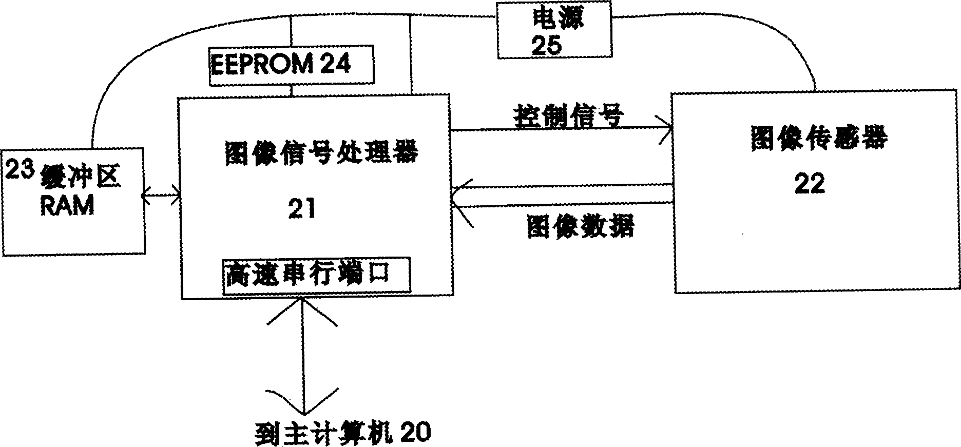
[0054] This embodiment is identical with embodiment 1 on hardware structure, and difference is that the image recognition function in the driver program 15 among the embodiment 1 is to finish in the image signal processor 21 of respective video camera, and video camera passes to host computer 50 It is not image data, but the position coordinates of the recognized pointer in the pixel sequence, and then the driver 15 completes the relevant coordinate transformation and calculation of relative coordinates, and calculates the coordinate information of the pointer 17 in the touch interval 60 for the computer 50 operating systems are used.


PUM


Abstract

Present invention refers to size variable touch system based on image recognition. It utilizes a length fixing or alterable rod, respectively installing two cameras on two ends of said rod, two camera viewing field forming overlapping on touch interval constituting a rectangular zone of vision using two camera as neighboring vertices and covering touch interval, two cameras direct coupling to host computer through USB 1394 etc high-speed serial buses, camera collected image data sent to host computer, relevant driving program proceeding image recognition, when identifying user's fingertip or what other similar touch indicator, utilizing coordinate transformation algorithm to determine indicator relative position on touch surface.

Description

technical field [0001] The present invention relates to a computer input device, and more particularly, it relates to a variable-size touch system based on image recognition. Background technique [0002] Currently known touch screens include four types: resistive touch screens, capacitive touch screens, surface acoustic wave touch screens, and infrared touch screens. [0003] The technical principle of the resistive touch screen is: the screen body of the resistive touch screen is composed of multi-layer conductive composite films, and each conductive layer is separated by many small transparent isolation points. When a finger touches the screen, a contact point appears between the two conductive layers, and the controller detects After the contact, perform A / D conversion to obtain the coordinates of the touch point. Resistive touch screens are unaffected by dust, water, and dirt. The conductive coating of the resistive touch screen is relatively thin and easy to break. I...

Claims


Application Information

Patent Timeline
Patent Type & Authority Applications(China)
IPC IPC(8): G06F3/041
Inventor 邢休东李瑞良
Owner 邢休东
Learn More