

Acoustic frequency directional ultrasonic wave Loudspeaker
An audio directional and ultrasonic technology, applied in the field of speakers and electronics, can solve the problems of large distortion, large mutual interference, and large occupation area of audio directional speakers, and achieve the effects of good vibration consistency, large mutual interference, and large occupation area.
Inactive Publication Date: 2006-08-02
UNIV OF ELECTRONICS SCI & TECH OF CHINA
View PDF0 Cites 12 Cited by
- Summary
- Abstract
- Description
- Claims
- Application Information
AI Technical Summary
Problems solved by technology
[0009] The audio frequency directional ultrasonic loudspeaker provided by the present invention can overcome the problems of existing audio frequency directional loudspeakers such as large distortion, poor stability, narrow bandwidth, large mutual interference, large occupied area, complex structure and high cost, and has good directivity, large sound pressure, Small distortion, good stability, high area utilization, simple structure, low cost and easy manufacturing
Method used
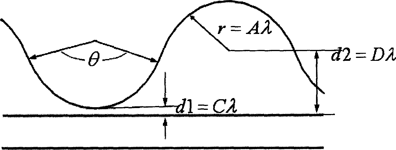
View moreImage
Smart ImageViewing Examples

Examples
specific Embodiment approach 1
[0034] Such as Figure 7 As shown, an audio frequency directional ultrasonic loudspeaker has a concave overall structure and is composed of a rectangular concave back panel and corresponding brackets and radiation materials. Its directional speaker area is fan-shaped that diverges outward.
specific Embodiment approach 2
[0035] Such as Figure 8 As shown, an audio frequency directional ultrasonic loudspeaker has a convex overall structure, which is composed of a rectangular convex back panel and corresponding brackets and radiation materials.
Login to View More PUM
 Abstract
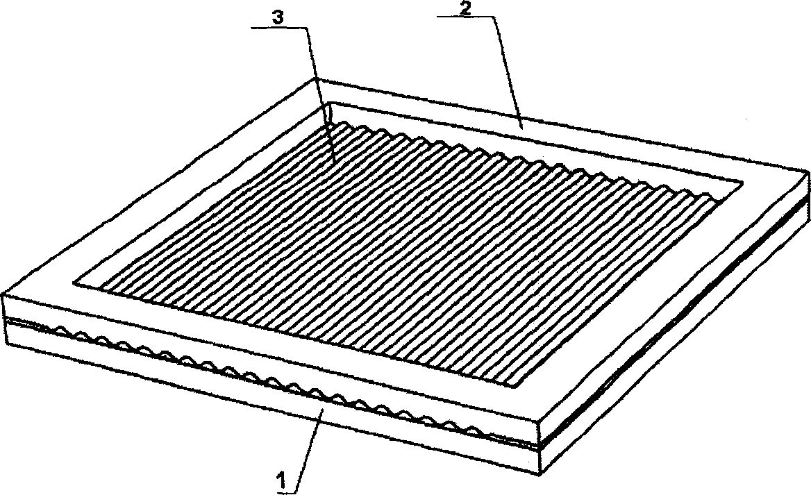
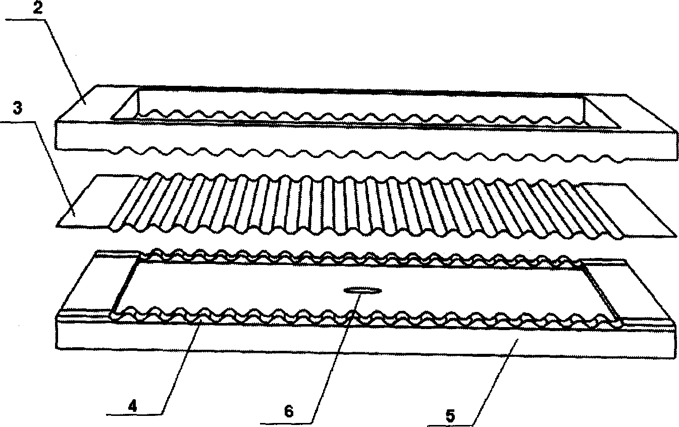
An ultrasonic loudspeaker of audio directing type is composed of supporting seat, pressing component and radiation material. It is featured as forming said supporting seat by carriage, back surface plate and air vent; setting carriage at periphery of back surface plate and placing radiation material on it closely as well as connecting its bottom to back surface plate; forming resonant cavity between radiation material and back surface plate; setting air vent at side-top of back surface plate and forming radiation material by three layers of ultrasonic film material.
Description
technical field [0001] An audio-frequency directional ultrasonic loudspeaker belongs to the field of electronic technology, in particular to the technical field of loudspeakers. Background technique [0002] The main characteristics of traditional loudspeakers are: 1) Based on a linear model, that is, the energy absorbed by the air medium is linearly related to the sound waves generated; 2) The sound propagation of traditional loudspeakers is divergent and does not have the characteristics of directivity; 3) Speakers radiate audible sound directly into the air. Therefore, the traditional loudspeaker must maintain the linear propagation relationship of the air medium when it is working. A simple summary is: the sound energy radiated by the speaker into the air must be within the range that the air molecules can maintain linear transmission. On the contrary, when the sound energy radiated by the speaker exceeds the requirements of the linear transmission of the air molecules,...
Claims
Login to View More Application Information
Patent Timeline
 Patent Type & AuthorityApplications(China)
IPC IPC(8): H04R17/00
Inventor徐利梅王袆焦丽华李应涛
OwnerUNIV OF ELECTRONICS SCI & TECH OF CHINA