Method for prepurifying air in an accelerated tsa cycle

An air and pre-purification technology, applied in chemical instruments and methods, separation methods, gas treatment, etc., can solve the problems of unobtainable gas flow, reduction of effective heat ratio, increase of system thermal inertia and dead volume, etc.

Inactive Publication Date: 2006-08-02
LAIR LIQUIDE SA POUR LETUDE & LEXPLOITATION DES PROCEDES GEORGES CLAUDE
View PDF9 Cites 21 Cited by
  • Summary
  • Abstract
  • Description
  • Claims
  • Application Information

AI Technical Summary

Problems solved by technology

[0057] However, from the above, such a gas flow rate is usually unavailable, because if such a high gas flow rate can be obtained, the PSA cycle should basically be selected instead of the TSA cycle
[0058] In addition, the proportion of effective heat is reduced because the metal mass associated with piping, valves, measuring and control instruments, and the corners of the adsorber remains constant, while the mass of adsorbent and impurities to be desorbed decreases due to the shortened cycle time , which is equivalent to greatly increasing the energy consumption of the entire purification method
[0059] Another disadvantage caused by increasing the regeneration gas flow rate is the increase in the pressure drop of the system, which also increases the energy consumption, unless the diameter of the adsorber is increased, which in turn increases the thermal inertia and dead volume of the system, etc.

Method used


Image

  • Method for prepurifying air in an accelerated tsa cycle
  • Method for prepurifying air in an accelerated tsa cycle

Examples


Embodiment Construction

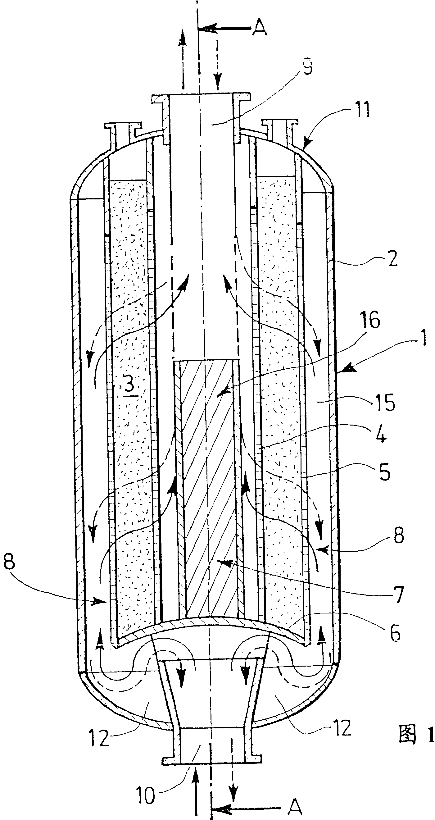
[0086] According to the invention, the reduction of thermal inertia is achieved by using one or more adsorbers 1 of the radial type, as shown in the accompanying drawing 1, which shows the adsorption along the axis A-A of an adsorber 1 applicable in the context of the present invention. Cross-section, wherein in the radial adsorber 1, the regeneration gas flows in the centrifugal direction, that is, flows from the center of the adsorber 1 to the periphery, and on the contrary, the gas to be purified flows in the centripetal direction, that is, flows from the adsorption The periphery of device 1 flows toward its center.

[0087] More precisely, air purified under a certain pressure is introduced to the side of the circumferential outer wall 2 of the adsorber 1 via a first orifice 10 located at the end 12 of the adsorber 1, wherein the adsorber contains The adsorbent in 3, the adsorbent bed 3 has a cylindrical three-dimensional shape with a hollow volume 16, that is to say, the ...


PUM


Abstract

The invention relates to a method for prepurifying air by means of adsorption in a TSA cycle, each recipient containing an adsorbent arranged on a radial adsorption bed, and each adsorption cycle consisting of (a) an adsorption stage during which the impurities are eliminated on the adsorbent at an adsorption temperature (rads), the air crossing the adsorption bed in a centripetal manner; (b) a regeneration stage during which the adsorbent is regenerated by flushing with a regeneration gas at a regeneration temperature (Treg), such as Treg>Tads, in order to desorb the impurities; et (c) an adsorbent cooling stage during which the temperature of the regenerated adsorbent is reduced. The maximum duration (rads) of the adsorption is 120 minutes, preferably between 60 and 120 minutes. The regeneration gas is introduced in such a way that it flushes the bed containing the adsorbent in the centrifugal direction. The maximum regeneration rate is 35% of the adsorption rate. The regeneration temperature is reached by means of a heat exchanger arrange outside the adsorber.

Description

technical field [0001] The present invention relates to a TSA process for prepurifying air to be subsequently fractionated by cryogenic processes. Background technique [0002] Traditionally, the air to be cryogenically distilled has been pre-dried, decarbonated and at least partially freed of the contained secondary air pollutants such as hydrocarbons, nitrogen oxides or similar substances. [0003] This method is often referred to as the air pre-purification method or simply the head purification method. [0004] The main purpose of this pre-cleaning is to retain and remove various atmospheric impurities that may be present in the gas stream until the content obtained is suitable for the cryogenic plant supplied with this air, regardless of the performance level or safety (requirement) of the plant. satisfactory operation. [0005] In fact, without such pretreatment, condensation and / or solidification of these impurities can occur during the cooling of the air to cryoge...

Claims


Application Information

Patent Timeline
Patent Type & Authority Applications(China)
IPC IPC(8): B01D53/04
CPCB01D2257/404B01D2253/104B01D2259/402B01D2257/702B01D2259/4009B01D2259/4146B01D53/0462B01D2257/80B01D2259/40052Y02C10/08B01D2259/416B01D2257/504B01D53/0431B01D2259/4006B01D53/261B01D2253/108B01D2259/40007Y02C20/40
Inventor C·赫梅吕克C·莫内罗
Owner LAIR LIQUIDE SA POUR LETUDE & LEXPLOITATION DES PROCEDES GEORGES CLAUDE
Why Eureka
Try Eureka