
Fluid bed granulation process and apparatus

一种流化床、冷却流化床的技术,应用在造粒装置,流化床造粒领域,能够解决成本效益负面影响、消耗大能源等问题

Inactive Publication Date: 2006-08-02
UREA CASALE SA
View PDF1 Cites 3 Cited by
  • Summary
  • Abstract
  • Description
  • Claims
  • Application Information

AI Technical Summary

Problems solved by technology

[0011] While there are advantages to both viewpoints, there are serious recognized disadvantages to fluid bed granulation processes of the type described above
[0012] In fact, in such a method, in addition to the need to supply a large amount of air in order to form and maintain the granulation fluidized bed, it is necessary to continuously supply a larger amount of air to form and maintain the cooling fluidized bed; energy, which negatively affects the cost-effectiveness of the method

Method used


Image

  • Fluid bed granulation process and apparatus
  • Fluid bed granulation process and apparatus

Examples


Embodiment Construction

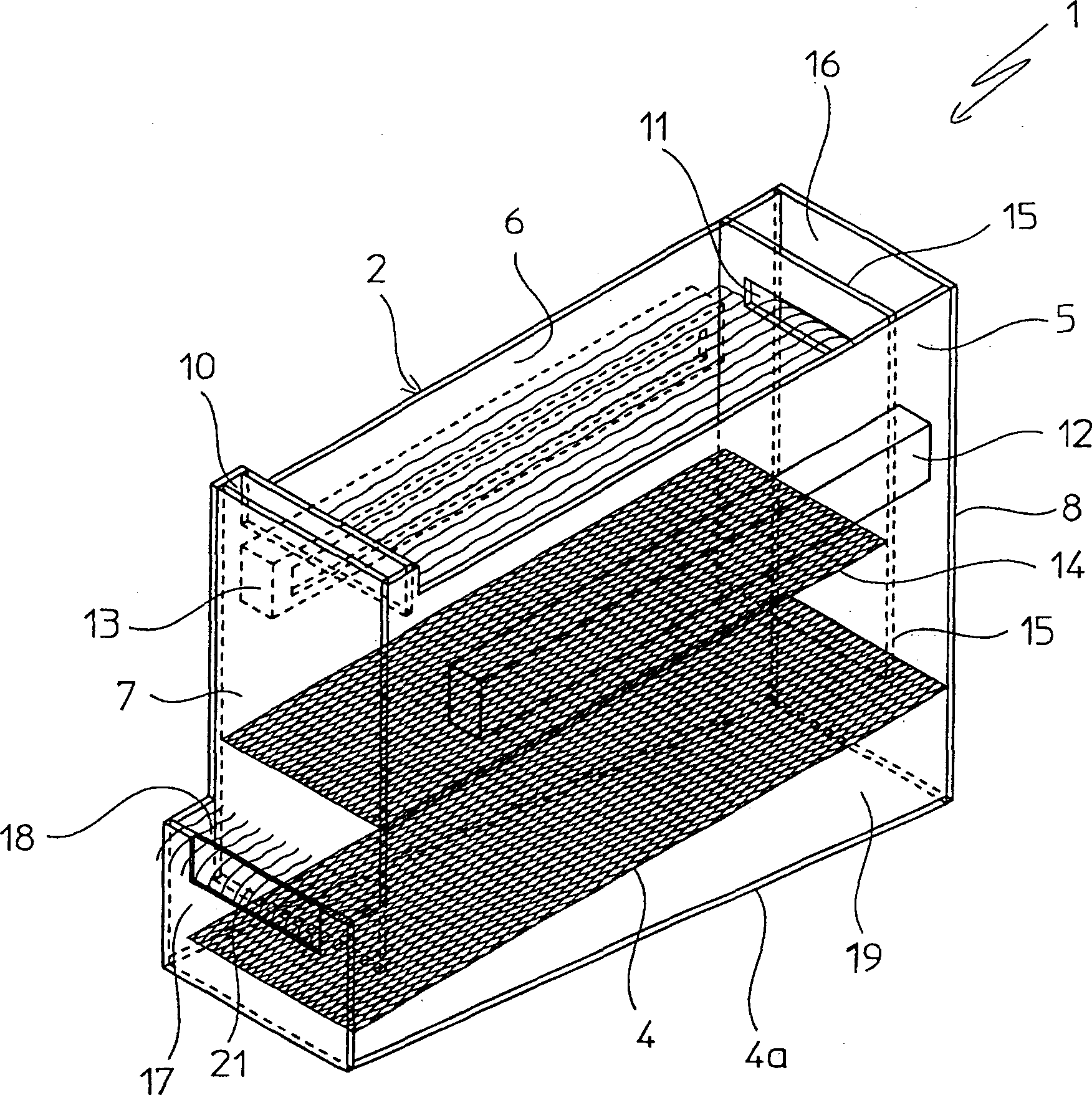
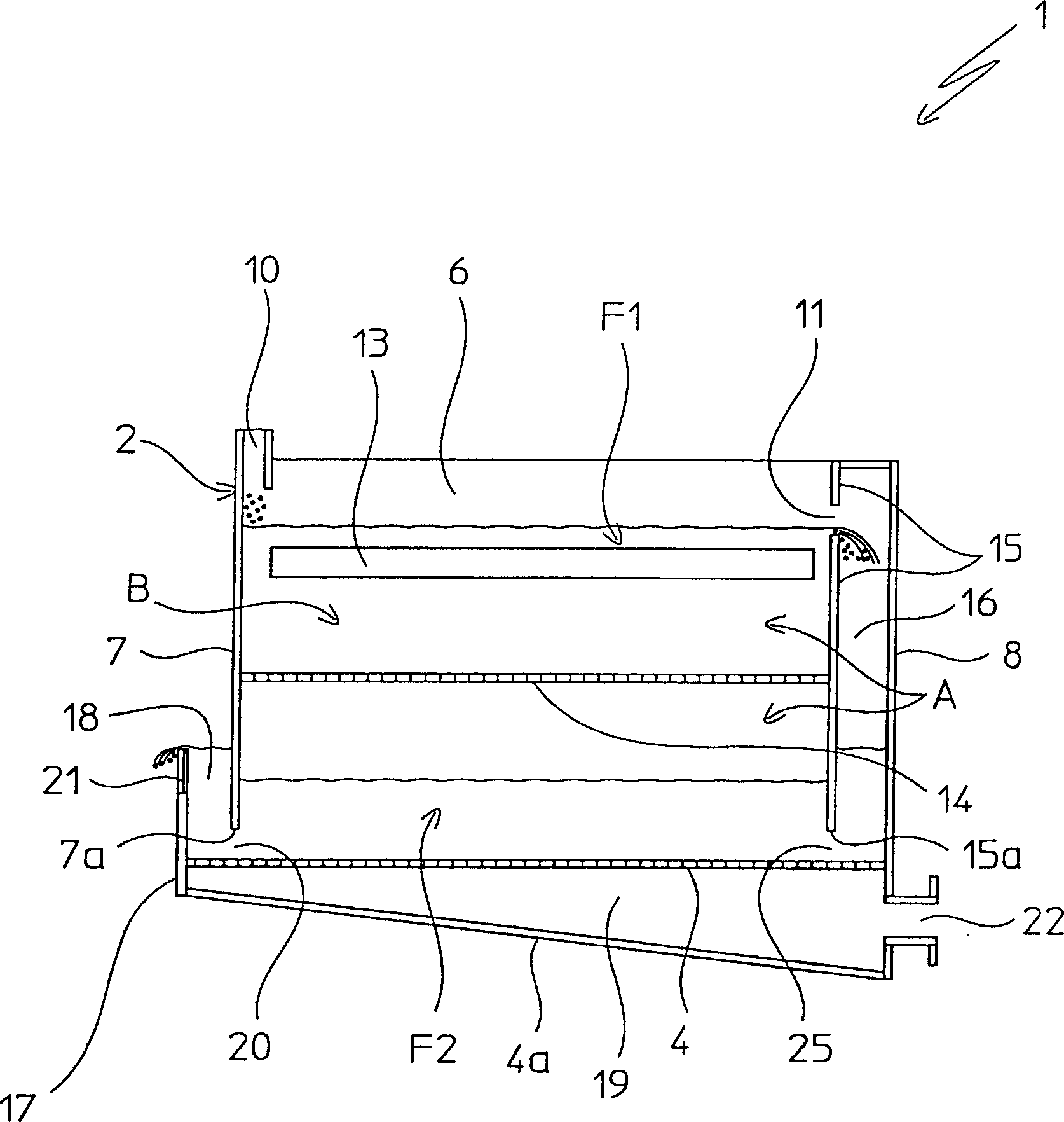
[0018] Referring to the accompanying drawings, the device for implementing the fluidized bed granulation method of the present invention is indicated by 1 as a whole.

[0019] The device consists of a self-supporting structure 2, substantially in the shape of a parallelepiped container, inside which delimits a space A in which are arranged two fluidized beds F1 and F2, which are described below will be more clear.

[0020] Said container structure 2 (hereinafter referred to simply as: container 2) has long side walls 5, 6, short front wall 7 (or top wall) and rear wall 8; The top is closed, and a double bottom plate is installed at the bottom of the container, and the upper bottom plate and the lower bottom plate are represented by 4 and 4a respectively.

[0021] According to a feature of the present invention, the top wall 7 of the container 2 has a bottom 7a separated from the bottom plate 4 of the double bottom plate, thereby defining a passage (or inlet and outlet) 20 so ...


PUM


Abstract

The present invention provides a fluid bed granulation process of an appropriate substance, comprising the cooling in a second fluid bed of the granules obtained. The same flow of fluidification air is used to form and support both fluid beds.

Description

technical field [0001] The bulk of the invention generally relates to the fluid bed granulation process of suitable materials such as urea, ammonium nitrate, ammonium chloride and similar readily granulated materials. [0002] In particular, the invention relates to a fluidized bed granulation process, wherein the granules obtained are cooled in a second fluidized bed, from which they are sent to storage and / or are packaged. [0003] The invention also relates to a granulation device for carrying out the above-mentioned method. Background technique [0004] In the fluidized bed granulation process, predetermined material granules are produced by continuous growth (in volume and mass) of a seed species of material continuously fed into said fluidized bed, and simultaneously fed with an appropriate flow of liquid growing material. acquired. The growing substance is a substance having the same properties as the substance being granulated, and is liquid, suitable for wetting, ...

Claims


Application Information

Patent Timeline
Patent Type & Authority Applications(China)
IPC IPC(8): B01J2/16B01J8/28
CPCB01J2/16
Inventor 吉安弗兰科·贝帝绨
Owner UREA CASALE SA
Learn More