Submersible water turbine

One type of water turbine, water wheel technology, applied in mechanical equipment, pipeline supports, pipes/pipe joints/pipe fittings, etc., can solve problems such as huge investment and damage to natural ecology

Inactive Publication Date: 2006-08-09
张留品
View PDF0 Cites 6 Cited by
  • Summary
  • Abstract
  • Description
  • Claims
  • Application Information

AI Technical Summary

Problems solved by technology

Water storage and damming will seriously damage the natural ecology. The more large-scale hydropower stations are built, the more serious the damage to the natural ecology will be. For example, the construction of the Three Gorges Dam requires a huge investment, and the gains and losses will wait for time to be tested.

Method used


Image

  • Submersible water turbine
  • Submersible water turbine
  • Submersible water turbine

Examples


Embodiment Construction

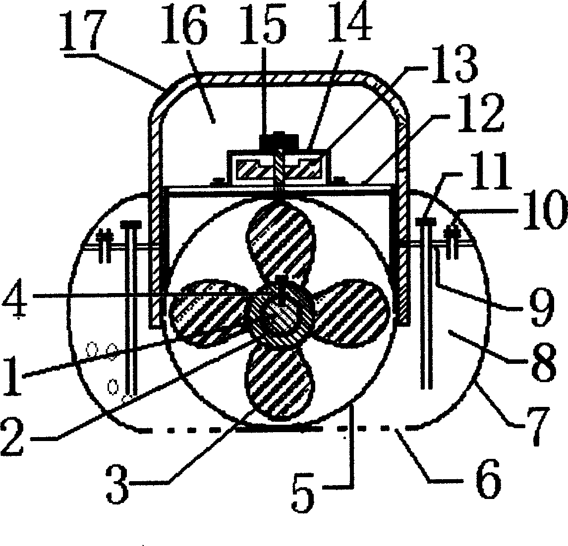
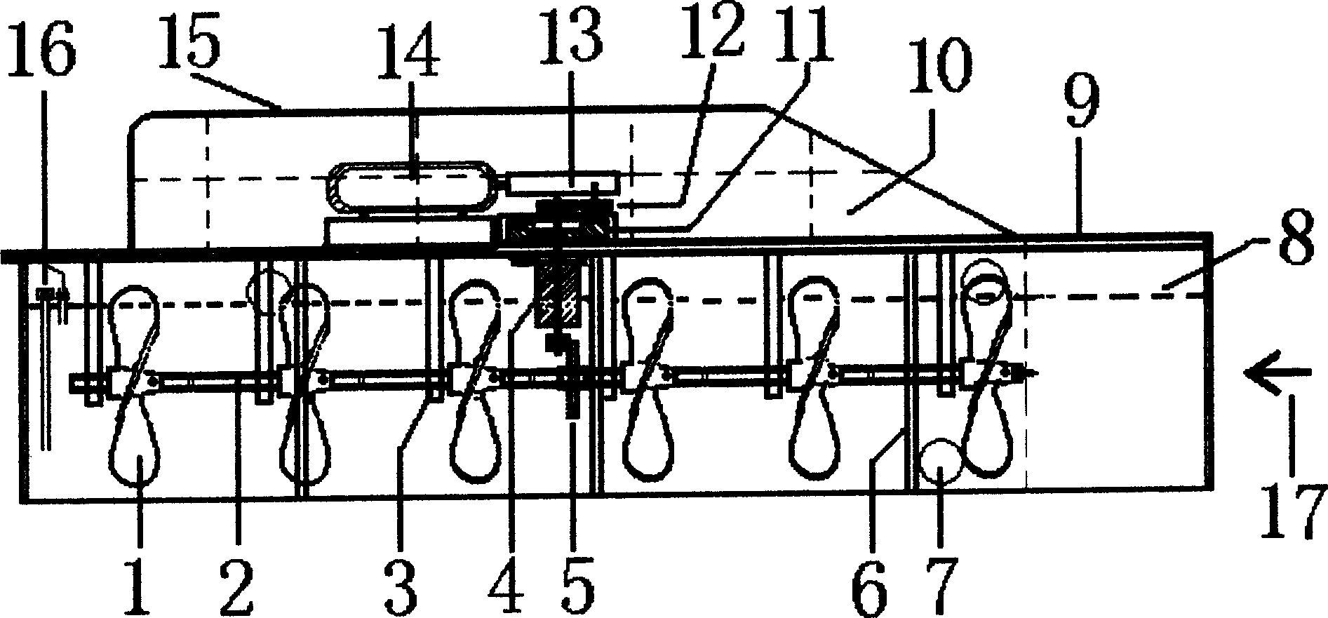
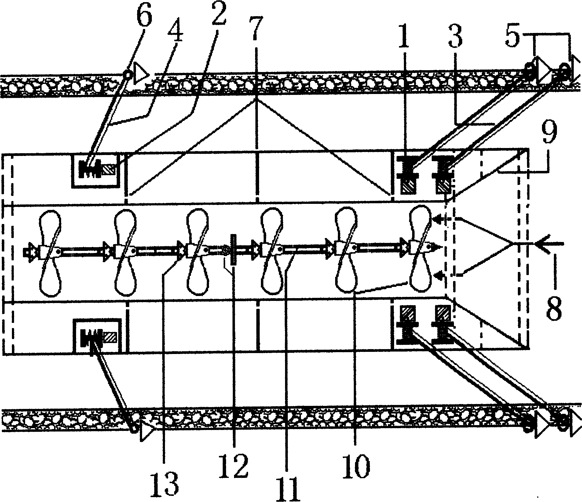
[0005] The specific structure and function of the submerged turbine are as follows figure 1 ., figure 2 . Shown. figure 1 .: Front view of submersible turbine structure: 1. Connect the central shaft of the turbine. 2. The connecting piece when connecting the propeller. 3. The paddle. 4. Lock the bolt. 5. A relatively closed cylindrical pipe outside the turbine. 6. The open bottom of the ship-shaped pontoon. 7. The outer wall of the ship-shaped pontoon. 8. The internal space of the ship-shaped pontoon. 9. The bottom bulkhead of the ship-shaped pontoon. 10. The short pipe installed at the bottom of the ship and a switch installed above the short pipe. 11. The long pipe installed at the bottom of the ship and the air pump installed above the long pipe. 12. The cabin floor. 13. Inertial flywheel. 14. Support frame. 15. Gear coaxial with inertial flywheel. 16. Operation room. 17. The ceiling of the operating room. figure 2 .: 1. Paddle type water wheel (six). 2. The bottom of the s...


PUM


Abstract

Said invention discloses an impeller type turbine impeller type turbine device utilizing reproducible nature (advection) hydroenergy generation of electricity. It combines diving ship type floating camel, impeller type turbine set, inertia flywheel, speed-up gears box, concentrating water flow entering relative closed cylinder type pipe, in turn impulsion plurality of paddle type waterwheel connected on parallel middle axle to generate electricity. Said invention has no pollution to environment.

Description

Technical field: [0001] A hydraulic turbine, specifically, a paddle-type hydraulic turbine that develops and utilizes renewable natural (advection) water energy. Background technique: [0002] Existing hydropower turbines must have high heads, dams need to be built to store water and accumulate energy for livestock. Water storage and dam construction will seriously damage the natural ecology. The larger the construction of large hydropower stations, the more serious the damage to the natural ecology. For example, the construction of the Three Gorges Dam requires huge investment, and the gains and losses will still be tested by time. There are also many inventions and utility models disclosed in the development and utilization of natural (advection) water energy: such as utility model: River Floating Water Turbine Generating Station, <Name of Invention>River floating water turbine power station and so on. Summary of the invention: [0003] The present invention is also a de...

Claims


Application Information

Patent Timeline
Patent Type & Authority Applications(China)
IPC IPC(8): F16L7/00
Inventor 张留品
Owner 张留品
Why Eureka
Try Eureka