

Illumination and illuminator with light as conduction
A technology of sunlight and light guide, applied in the field of storage and utilization of solar light sources, can solve problems such as pollution and hazards, and achieve the effects of strong operability, convenient promotion, and high light transmittance
- Summary
- Abstract
- Description
- Claims
- Application Information
AI Technical Summary
Problems solved by technology
Method used
Image

Examples
Embodiment 1
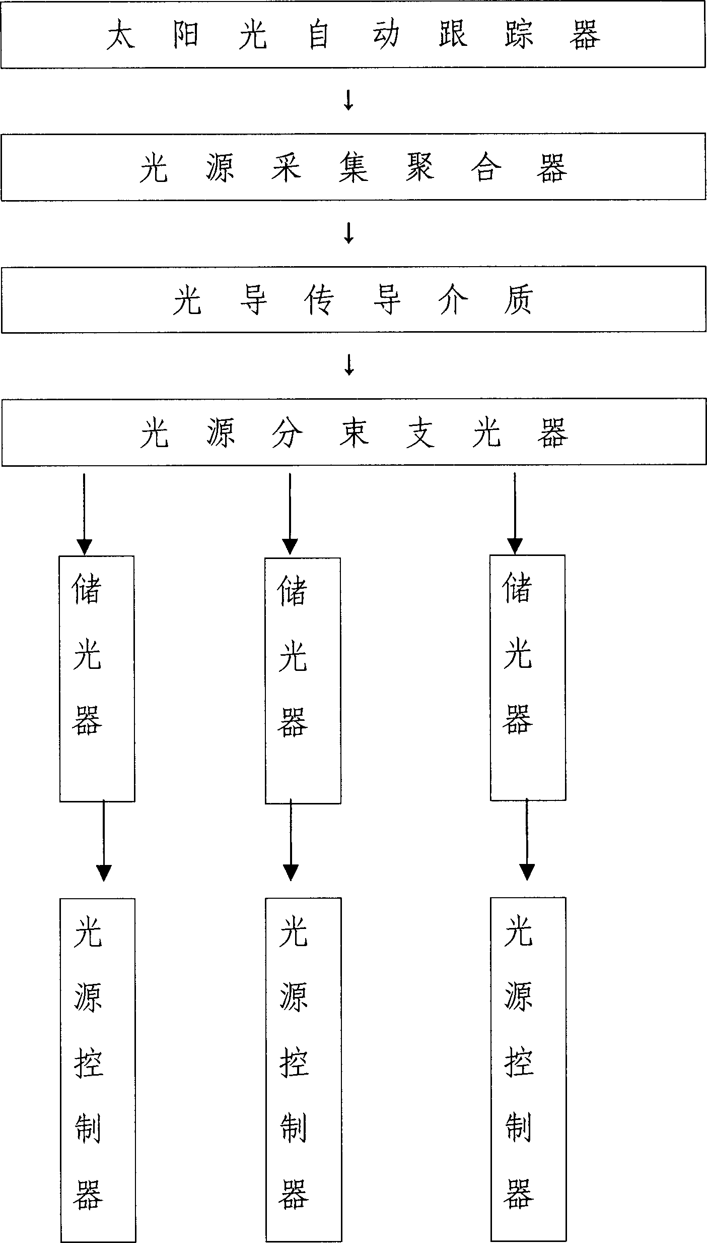
[0028] Plastic is used as the light guide medium, and the whole system is manufactured according to the following process requirements:
[0029] (1) Drive the electric transmission device with the signal output by the photosensitive controller, so that the target surface can receive the sun light source to the maximum extent.
[0030] (2) After the collected light source is processed through a dust-free process, it is focused into a beam and reflected to the collecting and branching beam to form a beam.
[0031] (3) The light beam penetrates the high-purity liquid surface for heat dissipation treatment and then enters the interface of the plastic light guide medium. Through the total reflection of the outer coating, the light wave advances along the axis direction and reaches the exit of the other port of the light guide medium.
[0032] (4) Distributing the emitted light beams to several light storage devices made of aluminate light storage type materials through beam splitte...
Embodiment 2
[0035] Use high-purity fused silica as the light-conducting medium, and follow the following process requirements:
[0036] (1) The signal output by the photosensitive controller drives the electric transmission device, so that the target surface can receive the sun light source to the maximum extent.
[0037] (2) After the collected light source is processed through a dust-free process, it is focused into a beam and reflected to the collecting and branching beam to form a beam.
[0038] (3) The light beam is incident on the interface of the high-purity fused silica light-guide medium, and through the total reflection of the outer coating, the light wave advances along the axis direction and reaches the exit of the other port of the light-guide medium.
[0039] (4) Distributing the emitted light beams to several light storage devices made of silicate light storage type materials through beam splitters.
[0040] (5) The intensity of the light beam emitted from the light storag...
Embodiment 3
[0042] Use glass as the light guide medium, and follow the following process requirements:
[0043] (1) The signal output by the photosensitive controller drives the electric transmission device, so that the target surface can receive the sun light source to the maximum extent.
[0044] (2) After the collected light source is processed through a dust-free process, it is focused into a beam and reflected to the collecting and branching beam to form a beam.
[0045] (3) The light beam is incident on the interface of the glass light guide medium, and through the total reflection of the outer coating, the light wave advances along the axis direction and reaches the exit of the other port of the light guide medium.
[0046] (4) Distributing the emitted light beams to several light storage devices made of sulfide light storage type materials through beam splitters.
[0047] (5) The intensity of the light beam emitted from the light storage device is regulated by a rotary mechanical...
PUM
| Property | Measurement | Unit |
|---|---|---|
| Diameter | aaaaa | aaaaa |
Abstract
Description
Claims
Application Information