Method and device for current limitation with an automatic current limiter

A current-limiting device and current-limiting technology, applied in relays, emergency protection devices, circuit-breakers with excessive current, etc. using electrodynamic effects, which can solve problems such as large current limiters, contamination of liquid metal, and wear and tear.

Inactive Publication Date: 2006-08-16
ABB RES LTD
View PDF6 Cites 7 Cited by
  • Summary
  • Abstract
  • Description
  • Claims
  • Application Information

AI Technical Summary

Problems solved by technology

Due to current limitation by means of arcs, large wear occurs in the current limiter and combustion residues can contaminate the liquid metal

Method used


Image

  • Method and device for current limitation with an automatic current limiter
  • Method and device for current limitation with an automatic current limiter
  • Method and device for current limitation with an automatic current limiter

Examples


Embodiment Construction

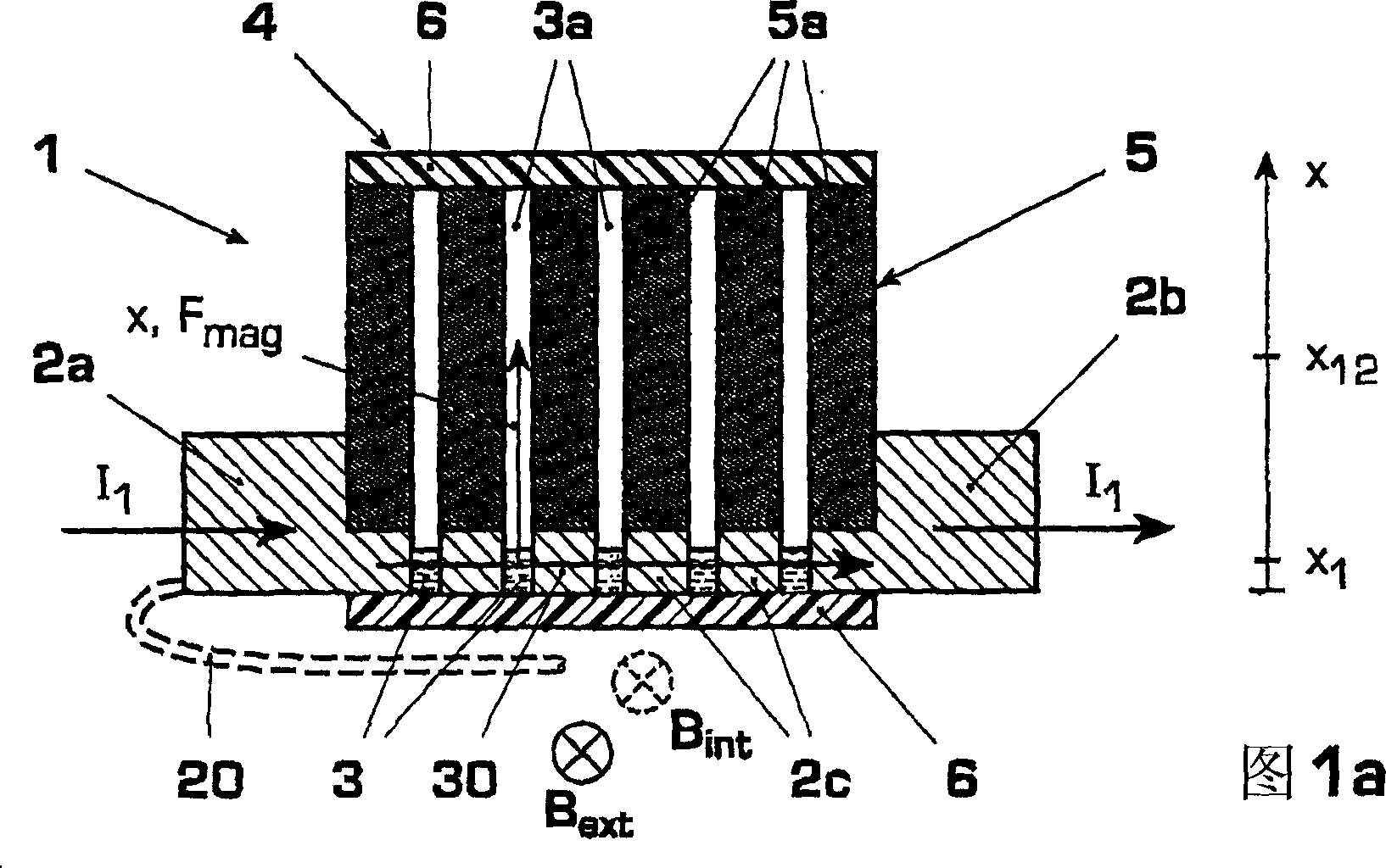
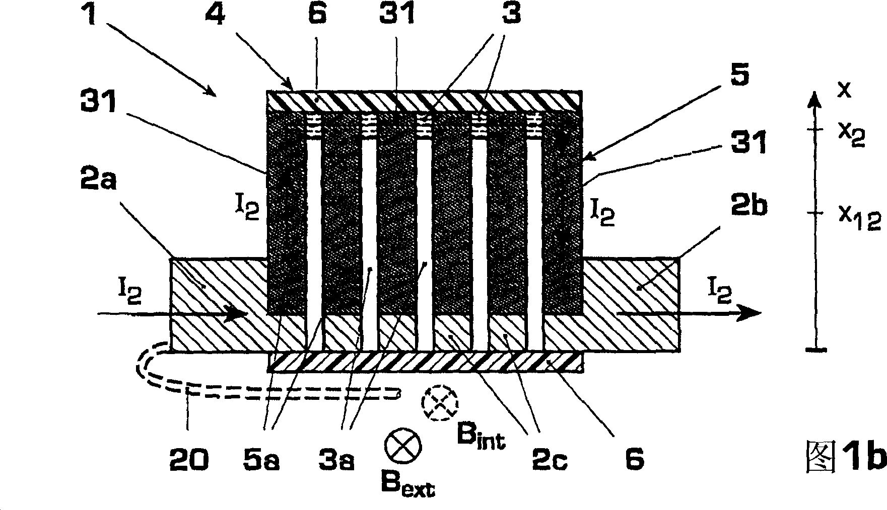
[0025] Figures 1a, 1b show an embodiment of a flow restrictor 1 of the liquid metal type. The current limiter 1 comprises solid metal electrodes 2 a , 2 b and an intermediate electrode 2 c for a current source 20 and a container 4 for liquid metal 3 . The container 4 has a bottom 6 and a cover 6 of electrically insulating material, between which an electrical impedance device 5 with at least one channel 3a for the liquid metal 3 is arranged. Above the liquid metal body, for example, a protective gas, an insulating liquid (with a spare volume not shown in the figure) or a vacuum can be provided.

[0026] According to the invention, the liquid metal 3, or in general a movable electrode 3, is connected to the overcurrent electrode I to be limited. 2 Automatic electromagnetic interaction is driven. In the case of liquid metal 3, the liquid metal remains in a liquid aggregate state and is arbitrarily at different positions x by forced movement 1 、x 12 or x 2 to move between. ...


PUM


Abstract

The invention relates to a method and a device (1) for combined current limitation and power breaking and to a switchgear having said device (1). In a combined current limiter / power braker (1) according to the invention, a movable electrode (3, 3') is guided automatically along a resistance element (5) for the current limiting path (31) by an overcurrent-dependent force (Fmag) for the purpose of current limitation and brought to an insulator (8) in a serial arrangement for power breaking purposes. Examples of embodiments are, inter alia, the utilization of Lorenz force for automatic current limitation; movable electrodes (3, 3') realized by means of liquid metal (3) or a movable solid conductor (3'); an electrical resistance (RX) increasing non-linearly in the direction of movement (x) for smooth power limitation characteristics and a resistance element (5) in the form of a dielectric matrix (5) with several channels (3a) for the liquid metal (3). Amongst the advantages achieved are electric arc-free, reversible current limitation and power breaking, which is also suitable for high voltages and currents, rapid reaction times, little wear and easy maintenance.

Description

technical field [0001] The present invention relates to the main technology for electrical switchgear, especially the main technology for limiting fault current in high voltage, medium voltage or low voltage switchgear. The invention is based on a current limiting method and device as described in the preambles of the independent claims and a switching device having the device. Background technique [0002] DE4012385A1 discloses a current-controlled disconnecting device whose operating principle is based on the constriction effect with liquid metal. Between two solid metal electrodes there is a single narrow channel filled with liquid metal. When there is an overcurrent, the liquid conductor should be contracted by the electromagnetic force through the contraction, so that the current itself contracts and separates the liquid conductor. The displaced liquid metal is collected in a storage container and reflowed after an overcurrent occurs. The separation of the contacts t...

Claims


Application Information

Patent Timeline
Patent Type & Authority Applications(China)
IPC IPC(8): H01H77/10H01H29/00H01H53/08
CPCH01H77/10H01H53/08H01H29/006H01H29/04
Inventor 卡韦赫·尼亚耶什弗里德里希·柯尼希
Owner ABB RES LTD
Why Eureka
Try Eureka