Method for measuring solution conductivity
A measurement method and conductivity technology, which is applied in the field of electrochemical measurement, can solve the problems of difficult calibration, restricting the measurement range of the conductivity cell, and affecting the measurement accuracy of the conductivity of the solution, so as to expand the measurement range and reduce the capacitive effect and polarization effect. Effect
- Summary
- Abstract
- Description
- Claims
- Application Information
AI Technical Summary
Problems solved by technology
Method used
Image

Examples
Embodiment 1
[0039] What this embodiment 1 introduces is the method for measuring conductivity of the present invention.
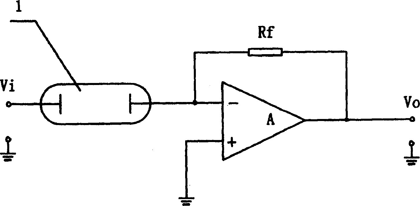
[0040] see figure 2 , the conductivity measurement circuit is basically the same as the existing conventional measurement circuit, and 1 is a conductivity cell. One electrode of the conductivity cell 1 is connected to the reverse terminal of the operational amplifier A, and a resistor R is connected between the reverse terminal of the operational amplifier A and the output terminal f , the positive end is grounded, and an AC square wave signal V with a stable amplitude and a half-cycle pulse width of t is added to the conductivity cell 1 i , measuring the output voltage V of the operational amplifier A 0 .
[0041] see image 3 , apply an AC square wave signal V with a half cycle pulse width t to the two poles of the conductivity cell 1 i , whose waveform is as image 3 a, by measuring the current signal of conductivity cell 1 in the range of 0-49%t in any half ...
Embodiment 2
[0047] What this embodiment 2 introduces is the method for measuring resistivity of the present invention.
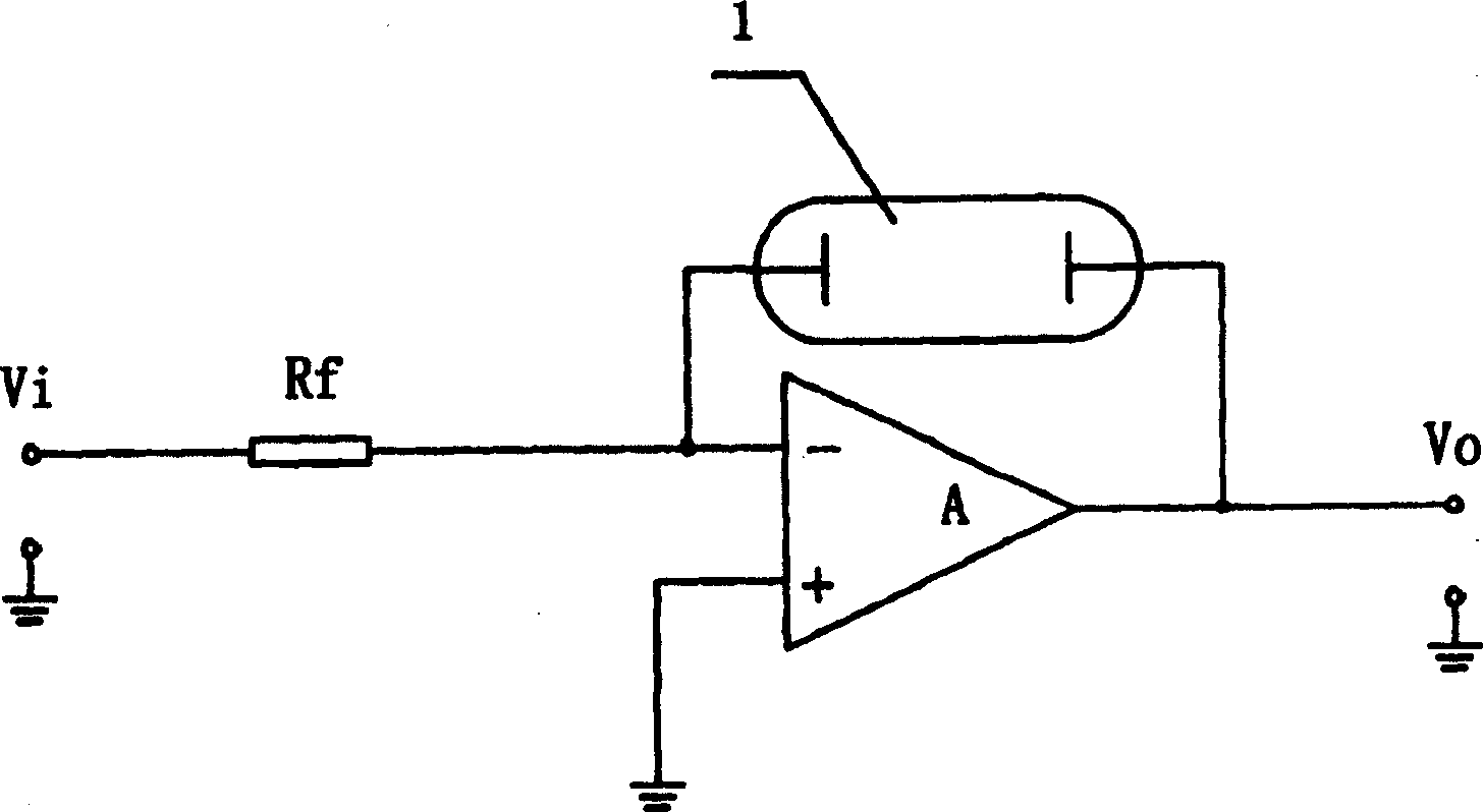
[0048] see Figure 4 , The resistivity measurement circuit is basically the same as the existing conventional measurement circuit, and 1 is a conductivity cell. The two electrodes of the conductivity cell 1 are connected between the inverting terminal of the operational amplifier A and the output terminal, and the inverting terminal of the operational amplifier A is also connected with a resistor R f . The positive end of the operational amplifier A is grounded, and an AC square wave signal V with a stable amplitude and a half-cycle pulse width of t is added to the resistor Rf i , measuring the output voltage V of the operational amplifier A 0 .
[0049] see Figure 5 , apply an AC square wave signal V with a half cycle pulse width t to the two poles of the conductivity cell 1 i , whose waveform is as image 3 a, by measuring the voltage signal of conductivity ce...
PUM
 Abstract
Description
Claims
Application Information
 - R&D
- Intellectual Property
- Life Sciences
- Materials
- Tech Scout
- Unparalleled Data Quality
- Higher Quality Content
- 60% Fewer Hallucinations
Browse by: Latest US Patents, China's latest patents, Technical Efficacy Thesaurus, Application Domain, Technology Topic, Popular Technical Reports.
© 2025 PatSnap. All rights reserved.Legal|Privacy policy|Modern Slavery Act Transparency Statement|Sitemap|About US| Contact US: help@patsnap.com