Energy saving control system of rubber injection shaping machine

An energy-saving control system and rubber injection technology, applied in the direction of jet flow program control, comprehensive factory control, comprehensive factory control, etc., to achieve the effect of on-site digital management, fast response of frequency conversion speed regulation, and remote control of energy saving

Inactive Publication Date: 2006-08-30
宁波千普机械制造有限公司
View PDF1 Cites 9 Cited by
  • Summary
  • Abstract
  • Description
  • Claims
  • Application Information

AI Technical Summary

Problems solved by technology

[0003] The purpose of the present invention is to design a method to directly monitor the process parameters in the process of operation in order to solve the problems existing in th

Method used


Image

  • Energy saving control system of rubber injection shaping machine
  • Energy saving control system of rubber injection shaping machine
  • Energy saving control system of rubber injection shaping machine

Examples


Embodiment Construction

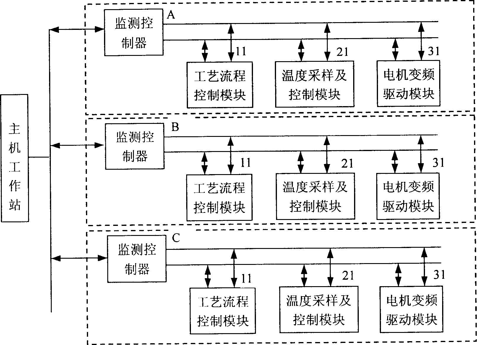
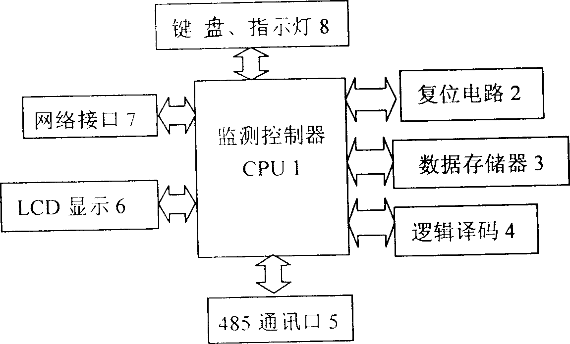
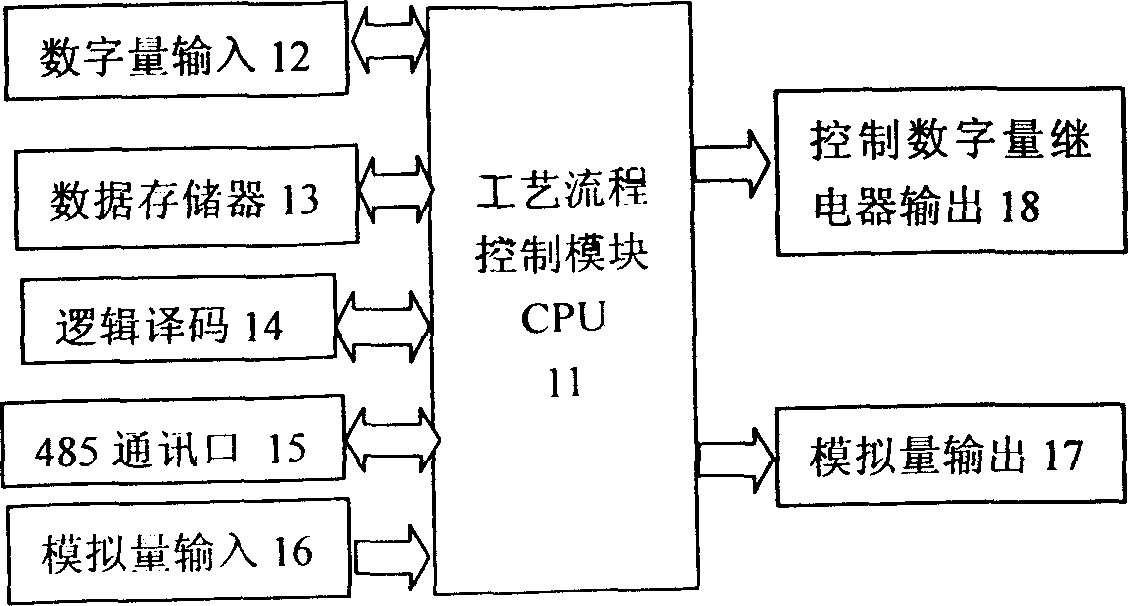
[0030] Monitoring controller (A, B, C...) structure, see figure 2 and image 3 The monitoring controller 1 is composed of reset circuit 2, data memory 3, logic decoding 4, 485 communication port 5, LCD display 6, network interface 7 and keyboard indicator light 8 respectively connected to its input terminal and output terminal.

[0031] Monitoring and control main chip circuit 1: CPU chip is INTER80196KC.

[0032] Reset circuit 2: The reset circuit mainly uses IMP809 and diode D20, which can reset the system under abnormal conditions, so as to ensure the normal operation of the system.

[0033] Data memory 3: use memory chip 27C512 to expand program space, and use chip 28C256 to expand mold parameter storage space.

[0034] Logic decoding 4: use the chip GAL16V8 of LT Company for logic decoding, and select each chip to work.

[0035] 485 communication port 5: The interface uses chip 75LBC184, resistors R51, R52, R53, R54, R55, R56, R57, capacitors C51, C52 to form a standa...


PUM


Abstract

The present invention relates to a rubber injection moulding machine energy-saving control system. It includes frequency converter drive motor, liquid pressure and flow rate sensor, temperature sensor and power supply circuit. Its energy-saving control system is formed from monitoring controller, technological process control module, temperature sampling and control module and frequency converter drive control module. Said invention also provides the working principle and operation method of said system.

Description

technical field [0001] The invention relates to a frequency conversion energy-saving control system, in particular to a frequency conversion energy-saving control technology for a drive motor of a rubber injection molding machine, which realizes group centralized control and remote energy-saving supervision while controlling the process flow of the rubber injection molding machine. Background technique [0002] Due to changes in the working environment of various driving motors, their loads also change accordingly. Therefore, the energy waste caused by the difference between the fixed power output and the actual load has become one of the current energy-saving research directions for driving motors. In the hydraulic system of rubber injection molding machine, the principle of pump selection is generally based on the maximum flow of the system plus a certain margin. In the actual production process, the driving motor always drives the hydraulic pump at a stable speed to outpu...

Claims


Application Information

Patent Timeline
IPC IPC(8): B29C45/76B29C45/82G05B19/46G05B19/418
CPCY02P90/02
Inventor 金波李勇陈飞飞翁振涛
Owner 宁波千普机械制造有限公司
Why Eureka
Try Eureka