Supercharge Your Innovation With Domain-Expert AI Agents!

Reference voltage generator for use in display applications

A reference voltage and generator technology, applied in static indicators, instruments, etc., can solve the problems of large transistor cost, output voltage bias, cost and unrealistic LCD application

Inactive Publication Date: 2006-08-30
INTERSIL INC
View PDF3 Cites 5 Cited by
  • Summary
  • Abstract
  • Description
  • Claims
  • Application Information

AI Technical Summary

Problems solved by technology

To handle this switching rate, use the figure 2 The architecture shown would require relatively large transistors (which are relatively expensive) and high currents, making them impractical for LCD applications where cost and size are critical
Also, for the same digital code, the output voltage may have large offsets due to mismatches in the multiple DACs 220 and output buffers 230

Method used


Image

  • Reference voltage generator for use in display applications
  • Reference voltage generator for use in display applications
  • Reference voltage generator for use in display applications

Examples


Embodiment Construction

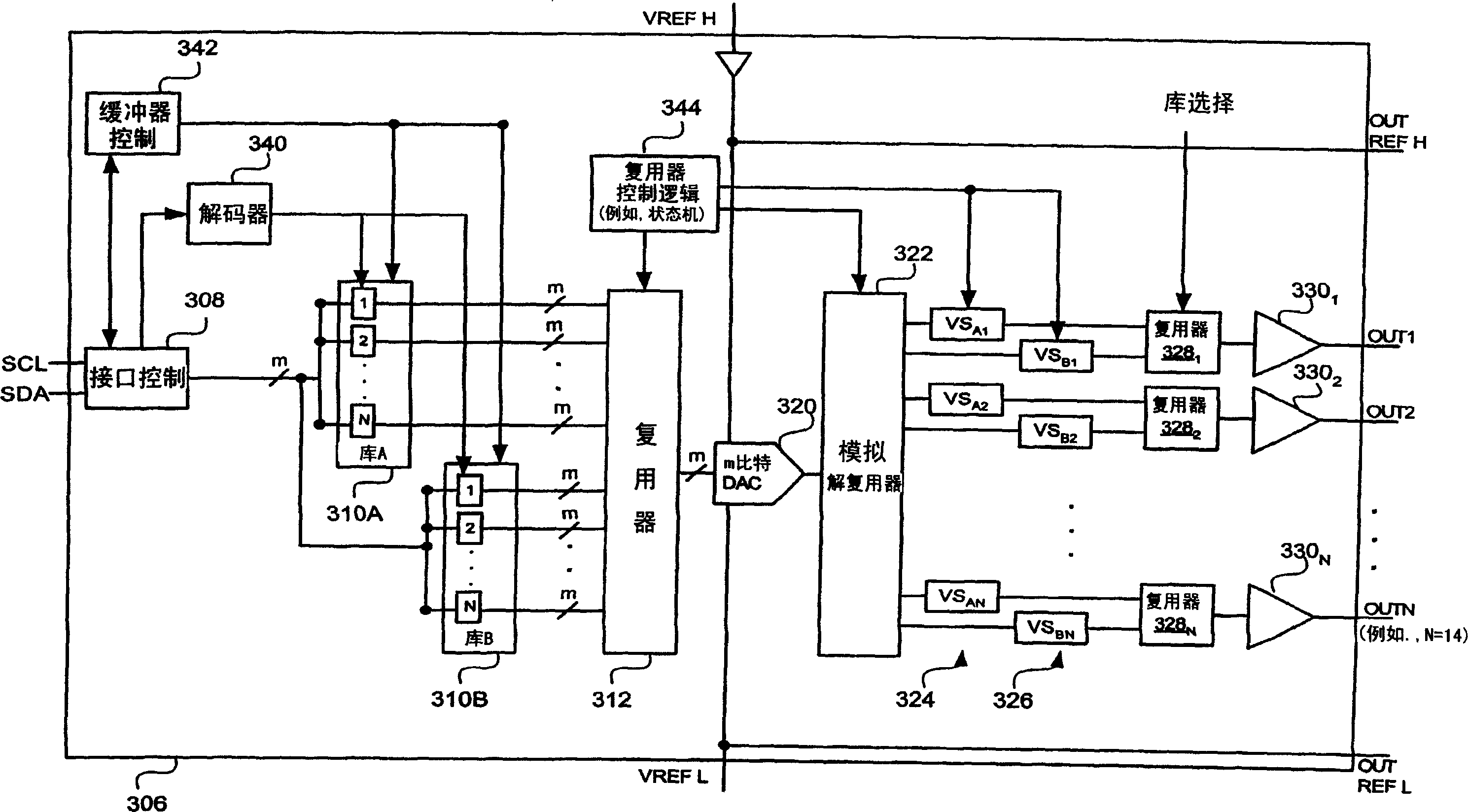
[0027] Figure 3AA reference voltage generator 306 according to an embodiment of the invention is shown. The illustrated reference voltage generator 306 includes an interface control 308 that implements an I2C interface in accordance with one embodiment of the present invention and thereby receives serial data (SDA) and Serial Clock (SCL). The illustrated reference voltage generator also includes a first register bank 310A (also referred to as Bank A) and a second register bank 310B (also referred to as Bank B), which are parallel to each other rather than serially ( figure 2 The banks 210 and 212 in are serial).

[0028] Interface control 308 also provides an output to decoder 340 which produces an output that cycles from 1 to N such that the first m-bit register in bank A (or bank B) receives display data 1 and the second m-bit register Display data 2 is received...and the Nth m-bit register receives display data N. Although both bank A and bank B are provided m bits at...


PUM


Abstract

A multi-reference voltage generator includes an interface controller, a first bank of N m-bit registers and a second bank of N m-bit registers. A first multiplexer has inputs connected to outputs of the first and second bank of registers. An m-bit digital-to-analog (DAC) has an m-bit parallel input connected to an output of the first multiplexer. An analog demultiplexer has an input connected to an analog output of the m-bit DAC. Each sample-and-hold circuit in a first group of N sample-and-hold (S / H) circuits is connected to a corresponding output of the analog demultiplexer. Similarly, each S / H circuit in a second group of N S / H circuits is connected to a corresponding output of the analog demultiplexer. N further multiplexers each have a first input connected to an output of a corresponding one of the S / H circuits in the first group and a second input connected to an output of a corresponding one of the S / H circuits in the second group. N output buffers, each have an input connected to an output of a corresponding one of the N further multiplexers, and an output useful for driving a column driver.

Description

[0001] priority claim [0002] This application claims priority from the following patent applications: U.S. Patent Application No. 11 / 344,899 filed February 1, 2006 by Chor Yin Chia; , US Patent Application No. 11 / 204,480; US Provisional Patent Application No. 11 / 344,899 filed by Chor Yin Chia on February 25, 2005. technical field [0003] Embodiments of the present invention relate to the field of integrated circuits, and more particularly to voltage generators useful in display (eg, LCD) applications. Background technique [0004] In conventional flat panel display systems, such as liquid crystal display (LCD) systems, the brightness of individual pixels or elements is controlled by transistors. Active matrix displays include a type of dot matrix of transistors (eg, thin film transistors) arranged in rows and columns. Column lines are coupled to the drains or sources associated with each transistor in each column. Row lines are coupled to respective gates associated wi...

Claims


Application Information

Patent Timeline
IPC IPC(8): G09G3/20G09G3/36G02F1/133
CPCG09G2320/0673G09G3/3614G09G3/3696
Inventor 谢楚贤
Owner INTERSIL INC
Features
  • R&D
  • Intellectual Property
  • Life Sciences
  • Materials
  • Tech Scout
  • Unparalleled Data Quality
  • Higher Quality Content
  • 60% Fewer Hallucinations
Learn More