Method and apparatus for forming surface shape, method and apparatus for forming flying surface shape of magnetic head

A technology of magnetic head and specified shape, applied in the directions of magnetic recording, maintaining head frame alignment, head hydrodynamic spacing, etc., can solve the problems of prolonging the manufacturing time, reducing the shape accuracy of the flying surface, increasing the manufacturing cost, etc., and reducing the manufacturing cost. , The effect of shortening the processing time and simplifying the forming process

Inactive Publication Date: 2006-08-30
SAE MAGNETICS (HK) LTD
View PDF1 Cites 0 Cited by
  • Summary
  • Abstract
  • Description
  • Claims
  • Application Information

AI Technical Summary

Problems solved by technology

[0006] Nevertheless, in the method for forming the flying surface of the magnetic head related to the prior art, since the coated protective layer is exposed and developed, it is difficult to form a very complicated shape, so it is difficult to correspond to this year and the future. More and more complex flight surface shapes
[0007] And, when forming each layer, the protective layer of respective coating is independently carried out exposure, developing operation, therefore, have the tendency of increasing the formation process of flying surface, increase magnetic head manufacturing time, and increase manufacturing cost
In addition, exposure and development must be performed each time the protective layer is formed, and it is labor-intensive to match its position, and the accuracy of the shape of the formed flight surface is also reduced, which in turn prolongs the manufacturing time.
[0008] Furthermore, it is necessary to prepare a plurality of reticle lines (masks) with predetermined patterns, thus increasing the manufacturing cost
In addition, in the exposure process, if the protective layer is thicker than the depth of focus of the imaging surface, a sharp end surface of the protective layer cannot be formed after development, and a steep wall angle of the concave-convex portion cannot be formed after etching.
Thus, it is difficult for such a head slider to maintain a stable flying height

Method used


Image

  • Method and apparatus for forming surface shape, method and apparatus for forming flying surface shape of magnetic head
  • Method and apparatus for forming surface shape, method and apparatus for forming flying surface shape of magnetic head
  • Method and apparatus for forming surface shape, method and apparatus for forming flying surface shape of magnetic head

Examples


Embodiment 1

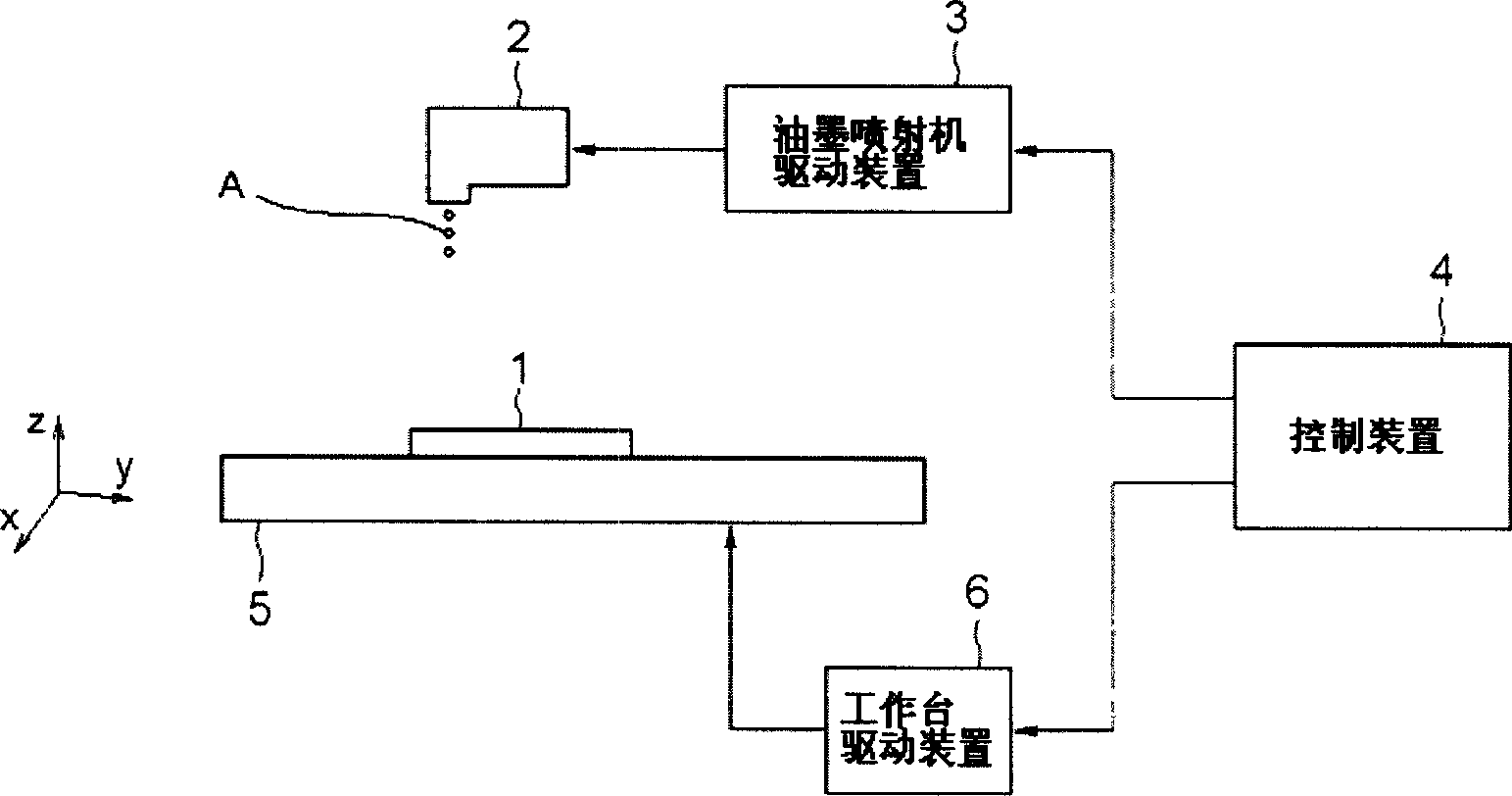
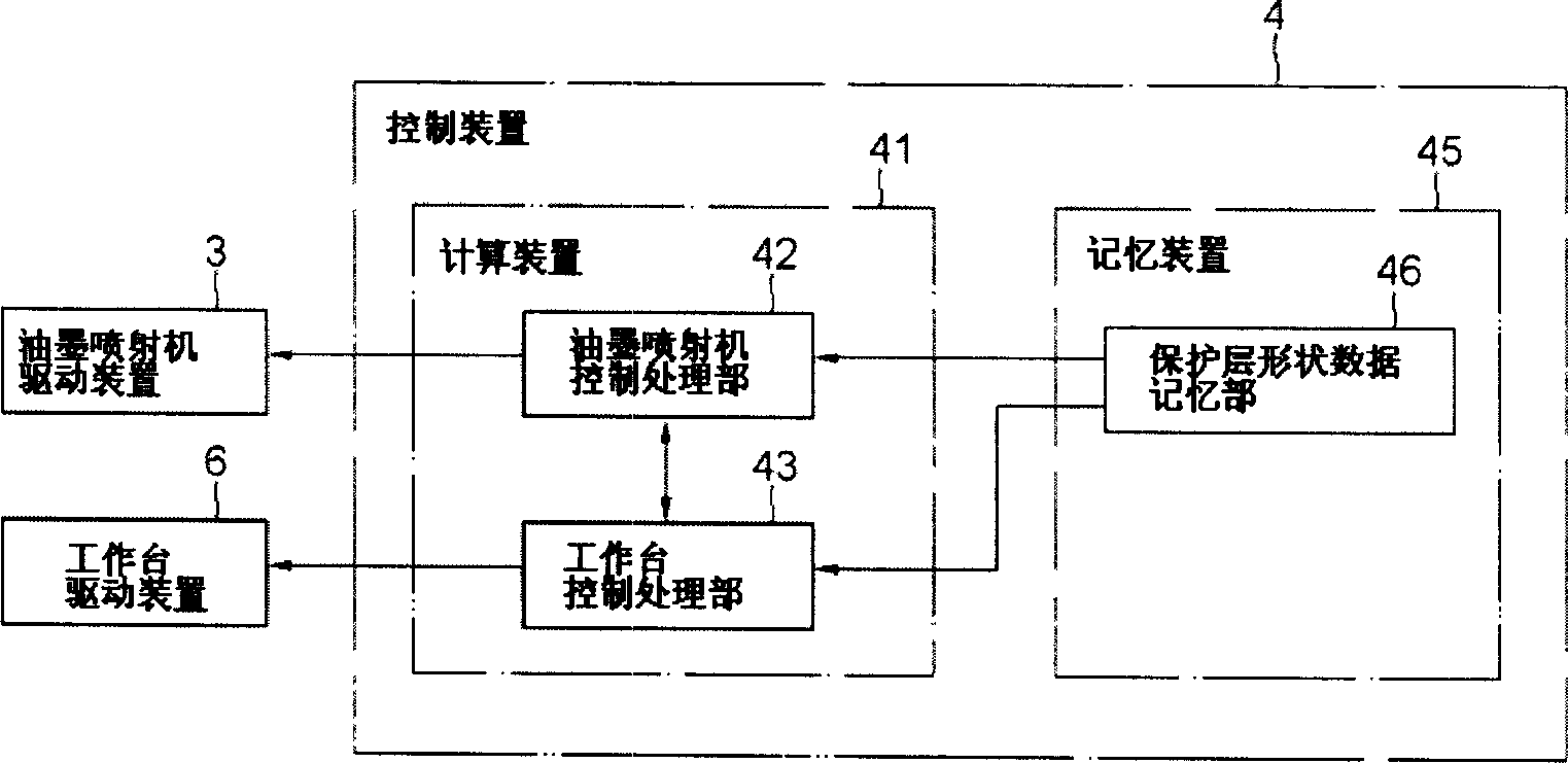
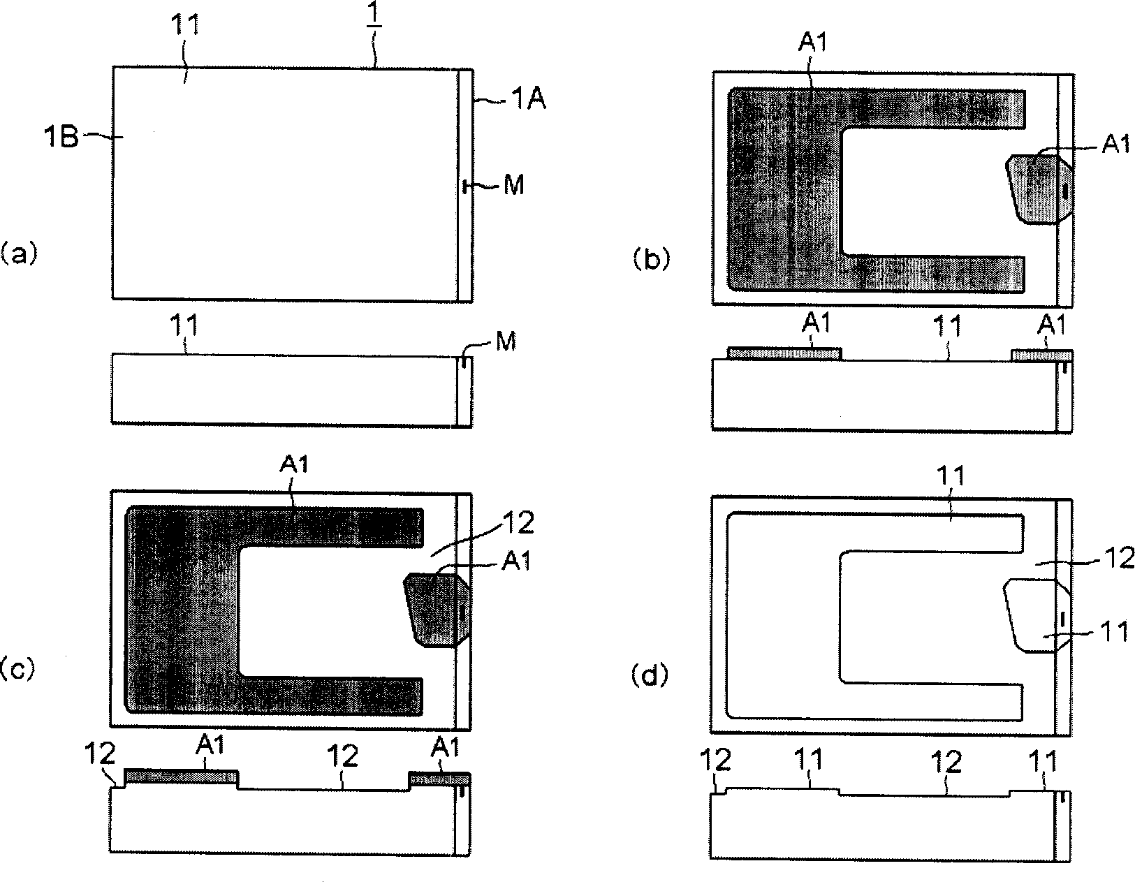
[0040] combine Figure 1 to Figure 5 As shown, the first embodiment of the present invention will be described. figure 1 It is a block diagram showing the structure of the magnetic head flying surface forming device. figure 2 It is a functional block diagram showing the structure of the control device. Figure 3 to Figure 4 It is an explanatory diagram showing the state when the flying surface of the magnetic head is formed. Figure 5 It is a flow chart of the operation of the surface shape forming device.

[0041] [constitute]

[0042] Such as figure 1 As shown, the flying surface forming device (surface shape forming device) of the magnetic head related to the present invention includes: the ink ejection device 2 (protective layer ejection device (protective layer forming device) for the protective layer material A of the protective layer formed by ejecting the protective layer of the prescribed shape to the magnetic head 1. device)), an ink jet driving device 3 that...

Embodiment 2

[0072] Next, combine Figure 6 to Figure 9 A second embodiment of the present invention will be described. Image 6 It is a block diagram showing the structure of the magnetic head flying surface forming apparatus. Figure 7 to Figure 8 It is an explanatory diagram showing the state when the flying surface of the magnetic head is formed. Figure 9 It is the flow chart of the operation of the flight surface forming device.

[0073] [constitute]

[0074] The magnetic head flying surface forming apparatus according to this embodiment further includes laser irradiation devices 7 and 8 (laser irradiation devices) for irradiating laser beams to the protective layer formed on the magnetic head 1 in addition to the structure described in the first embodiment. Correspondingly, the computing device 41 of the control device 4 includes a laser irradiation control processing unit (not shown) for controlling the operation of the laser irradiation devices 7 and 8 .

[0075] Specifically,...

Embodiment 3

[0091] combine Figure 10 Embodiment 3 of the present invention will be described. Figure 10 A shows a schematic diagram of the state when a protective layer is formed on the magnetic head 1 as an etching target, Figure 10 B is a schematic diagram of the state after etching. The process of forming the flying surface of the magnetic head using the above-mentioned method and apparatus for forming the flying surface is described below, but any method and apparatus may be used to form the shape of the magnetic head described below.

[0092] First, as described above, the protective layer material A is sprayed onto the magnetic head 1 by an ink jetting device, and a predetermined shape of the protective layer is drawn. Then, if Figure 10 As shown in A, the periphery of the protective layer A, that is, the corner (Corner) of the protective layer A is rounded and coated. Next, the flying surface of the magnetic head 1 on which the protective layer A is formed is dry-etched using an ...


PUM

PropertyMeasurementUnit
radiusaaaaaaaaaa

Abstract

An apparatus for forming a surface shape includes a resist forming device for forming a resist of a predetermined shape on a predetermined surface of the etching object, and an etching device for performing etching to the predetermined surface of the etching object on which the resist is formed. The resist forming device includes a resist discharging device for forming a resist of a predetermined shape by discharging a resist material to the predetermined surface of the etching object. The appararus can form a surface shape of an etching object in a short time at low cost, and to make the surface shape to be formed highly accurate.

Description

technical field [0001] The invention relates to a method and device for forming a surface shape, in particular to a method and a device for forming a protective layer and forming a surface shape by etching. Background technique [0002] A magnetic disk drive device (HDD) includes a magnetic head in which a magnetic head element portion for reading and writing data to a magnetic disk is formed. Moreover, in the current magnetic disk drive device, with the high density of recorded data, the magnetic head is required to be as close as possible to the surface of the magnetic disk, that is, the requirement for low floating of the magnetic head is getting higher and higher. [0003] In order to achieve low floating, unevenness of a predetermined shape is formed on the flying surface of the magnetic head by using the air flow flowing in when the magnetic disk rotates to generate appropriate heavy pressure. Moreover, in recent years, the shape of the flying surface has become more ...

Claims


Application Information

Patent Timeline
Patent Type & Authority Applications(China)
IPC IPC(8): G11B5/60G11B5/127
CPCC23F4/00G11B5/6005G11B5/6082
Inventor 伊藤善映中田刚上田国博
Owner SAE MAGNETICS (HK) LTD
Why Eureka
Try Eureka