Device for ultrasonic welding

A technology of ultrasonic welding and ultrasonic welding electrode, which can be used in welding equipment, non-electric welding equipment, metal processing equipment, etc., and can solve problems such as insufficient welding.

Inactive Publication Date: 2006-08-30
FORSCHUNG ENTWICKLUNG KLAUS DOBERNECKER ING GRAD
View PDF1 Cites 5 Cited by
  • Summary
  • Abstract
  • Description
  • Claims
  • Application Information

AI Technical Summary

Problems solved by technology

[0005] In fact, the aforementioned device has the disadvantage that, after the two anvils have been fully deflected relative to each other, in many cases after the application of corresponding ultrasonic energy, a sufficient weld cannot be achieved

Method used


Image

  • Device for ultrasonic welding
  • Device for ultrasonic welding
  • Device for ultrasonic welding

Examples


Embodiment Construction

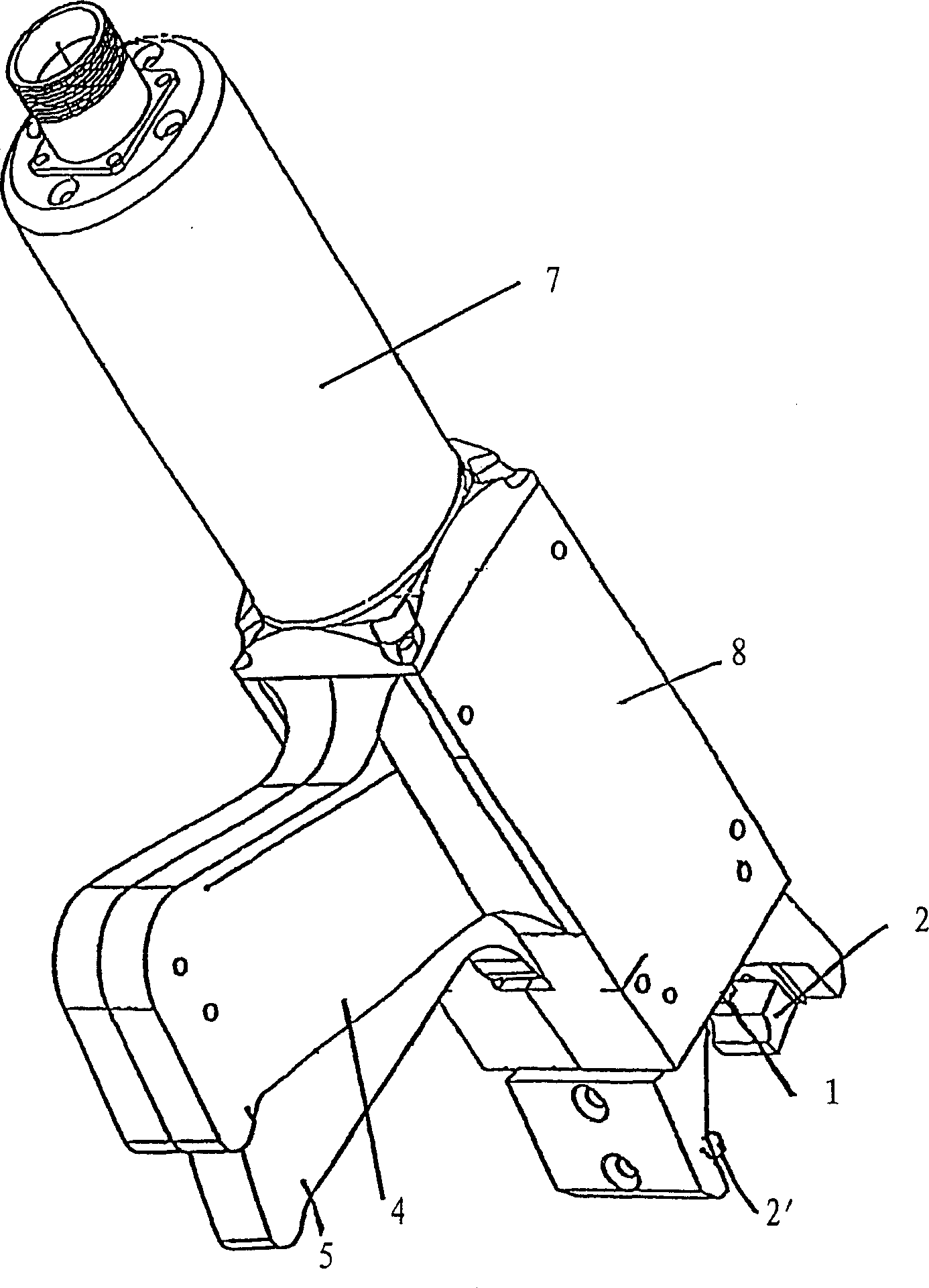
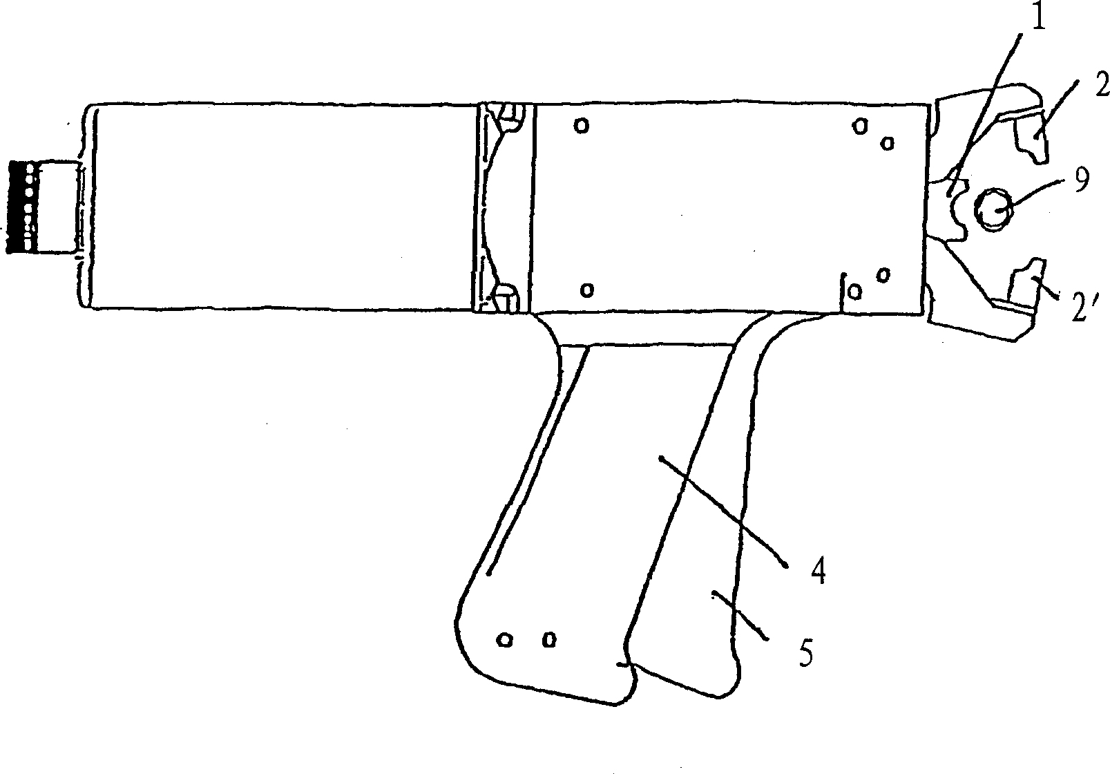
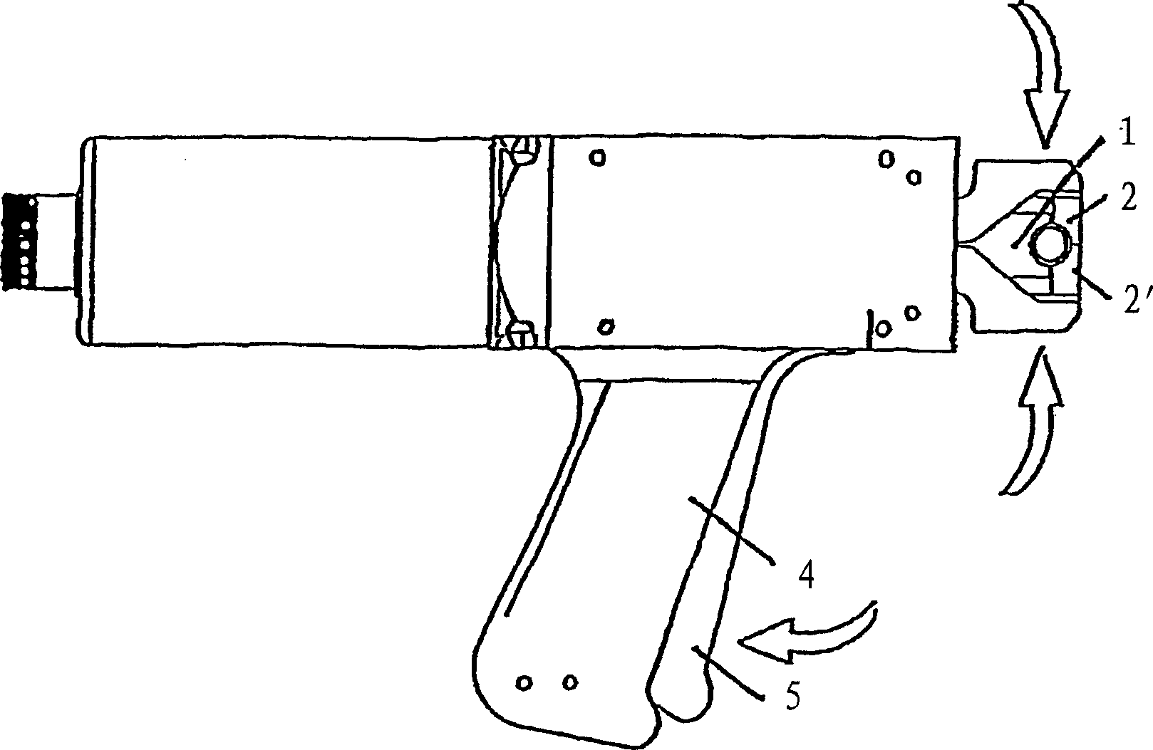
[0023] figure 1 Shown is an exemplary embodiment of a device according to the invention shown in a schematic perspective view. It mainly includes a sonotrode 1 that generates ultrasonic vibrations and two anvils 2, 2'. The two anvils and the sonotrode form a radial cross-section of the welded material in the welding state. Compression chamber bounded by sonotrode 1 and anvil 2, 2' to compress and / or slightly deform the material to be welded, such as a plastic corrugated hose, where the two anvils 2, 2' are positioned mutually Mobile and rotatable, the shape of the inside of the anvil 2, 2' is designed to be recessed.

[0024] The sonotrode 1 is excited via an oscillator (not shown in the figure), which transmits its energy to the sonotrode 1 largely inside the housing 8 via a pressurizer 7 .

[0025] In addition, the device according to the invention has a pistol-grip-shaped handle 4 on which a grip-shaped actuating element 5 is arranged.

[0026] After inserting a corrugat...


PUM


Abstract

A device for ultrasonic welding of electrical conductors includes an ultrasonic oscillation-producing sonotrode and two anvils, which as viewed in radial cross section of the article to be welded, form a compression chamber defined by the sonotrade and the anvils for compressing and/or slightly deforming the article to be welded. The two anvils are supported to be moveable relative to one another, such that the two anvils during pivotal movement toward one another, at least partly perform also a displacement movement in the direction of the sonotrode.

Description

technical field [0001] The invention relates to an ultrasonic welding device and its corresponding use. Background technique [0002] According to the state of the art, various devices are known for connecting electrical conductors, in particular in the form of stranded wires, in a compressed state. [0003] This aspect mostly refers to such equipment, on which the wires to be connected are put into a half-open chamber, so that the wires are then passed through a sonotrode generating ultrasonic vibrations and a corresponding electrode. Connect under compression. The compression chamber is delimited by the inner interface of the sonotrode and the counter electrode and other interface elements. [0004] According to the German patent DE 37 10 603 C2, there is known an ultrasonic welding device for metal wires or the like, which has a sonotrode which produces acoustic oscillations and two anvils, the two anvils and the sonotrode start from the transverse Viewed from the surf...

Claims


Application Information

Patent Timeline
Patent Type & Authority Applications(China)
IPC IPC(8): B23K20/10B29C65/08H01R43/02B29C65/00
CPCB23K20/10H01R43/0207B29C66/8167B29C66/80H01R43/0263B23K2201/32B29C66/5221B29C66/5261B29L2023/18B29C66/81463B29C66/1122B29L2023/005B29C66/861B29C65/08B29C66/8322B29C66/83241B29C66/8221B29C66/8242B23K2101/32B29C65/00
Inventor 克劳斯·埃克哈特·多博内克
Owner FORSCHUNG ENTWICKLUNG KLAUS DOBERNECKER ING GRAD
Why Eureka
Try Eureka