Forming mould for flue gas exhausting pipeline

A technology for forming molds and air pipes, which is applied in the direction of molds, vertical pipes, ceramic molding machines, etc., and can solve the problems of low product strength, low production efficiency, and easy breakage

Inactive Publication Date: 2011-10-12
韩文强
View PDF4 Cites 6 Cited by
  • Summary
  • Abstract
  • Description
  • Claims
  • Application Information

AI Technical Summary

Problems solved by technology

[0002] The existing flue gas exhaust pipe has a non-circular cross-section inner cavity, which is basically handmade, and the production efficiency is low. The horizontal prefabrication method is adopted, and the prefabrication site takes up a lot of space. Since the pipe wall of the flue gas exhaust pipe is 10— For thin-walled pipe

Method used


Image

  • Forming mould for flue gas exhausting pipeline
  • Forming mould for flue gas exhausting pipeline
  • Forming mould for flue gas exhausting pipeline

Examples


Embodiment 1

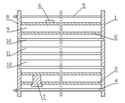
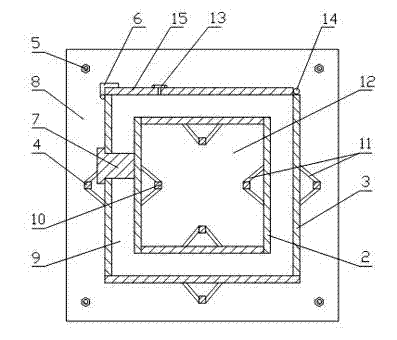
[0022] Example 1, such as figure 1 , figure 2 As shown, the exhaust gas duct forming mold includes a left frame 1 and a right frame 8, and a plurality of detachable outer templates 3 and inner templates 2 are arranged between the left frame 1 and the right frame 8. The detachable means: multiple outer templates 3 are respectively connected to the left frame 1 and the right frame 8 through fixing and limiting devices; multiple inner templates 2 are respectively connected to the left frame 1 through fixing and limiting devices with box 8 on the right. A plurality of outer templates 3 form an outer mold cavity, and a plurality of inner templates 2 form an inner mold cavity 12 in the outer mold cavity. A molding cavity 9 is formed between the inner and outer templates. The inner and outer contours of the cross-section of the molding cavity 9 are Square, at least one of the outer templates 3 is provided with a feed inlet 15, and the feed inlet 15 is provided with a door that can...

Embodiment 2

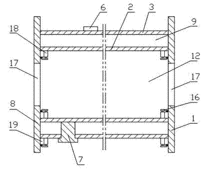
[0026] Example 2, such as image 3 , Figure 4 As shown, the exhaust gas duct forming mold includes a left frame 1 and a right frame 8, and a plurality of detachable outer templates 3 and inner templates 2 are arranged between the left frame 1 and the right frame 8. The detachable means: multiple outer templates 3 are respectively connected to the left frame 1 and the right frame 8 through fixing and limiting devices; multiple inner templates 2 are respectively connected to the left frame 1 through fixing and limiting devices with box 8 on the right. A plurality of outer templates 3 form an outer mold cavity, and a plurality of inner templates 2 form an inner mold cavity 12 in the outer mold cavity. A molding cavity 9 is formed between the inner and outer templates. The inner and outer contours of the cross-section of the molding cavity 9 are Square, at least one of the outer templates 3 is provided with a feed inlet 15, and the feed inlet 15 is provided with a door that can...

Embodiment 3

[0029] Example 3, such as Figure 5 As shown, the disassembly structure between the multiple inner and outer templates between the left frame 1 and the right frame 8 of the exhaust gas duct forming mold and the left frame 1 and the right frame 8, that is, the multiple inner and outer templates and the The fixing and limiting devices between the left side frame 1 and the right side frame 8 are the same as the aforementioned structures. The difference is that two inner mold cavities 12 are arranged in the outer mold cavity surrounded by a plurality of outer formworks 3. Of course, there can be more than two inner mold cavities 12 to form a conjoined smoke exhaust duct, and each inner mold cavity The shapes and sizes of the cavities 12 may be the same or different.

[0030] Such as Figure 6 The flue gas duct forming mold shown is provided with inner template grooves 20 and outer template grooves 19 for inserting multiple inner templates 2 and multiple outer templates 3 on the ...


PUM


Abstract

The invention discloses a forming mould for a flue gas exhausting pipeline, and the forming mould provided by the invention comprises a left side frame and a right side frame, wherein a plurality of external mould plates and internal mould plates, which are detachable, are arranged between the left side frame and the right side frame; an external mould cavity is defined by the plurality of external mould plates; an internal mould cavity is defined by the plurality of internal mould plates in the external mould cavity; forming cavities are formed between the external mould plates and internal mould plates; and a feed port is formed on at least one of the external mould plates. By using the forming mould provided by the invention, the mechanical mould production for a thin-wall flue gas exhausting pipeline can be realized, the problem that the mechanical production cannot be achieved in the field of forming of prefabricated noncircular thin-wall component is solved, the product is formed through one step, the production efficiency is increased, the labor intensity of a worker is reduced, places for production are greatly saved, the production process is supplemented by virtue of vibration molding, the product intensity and quality are high, and the quality fluctuation and the raw material waste which are caused by manual operation are reduced simultaneously.

Description

technical field [0001] The invention relates to the technical field of prefabricated molds for building facilities, in particular to a mold for forming exhaust gas pipes. Background technique [0002] The existing flue gas exhaust pipe has a non-circular cross-sectional inner cavity, which is basically hand-made, and the production efficiency is low. The horizontal prefabrication method is adopted, and the prefabrication site takes up a lot of space. Since the flue gas pipe wall is 10— For thin-walled pipes with a thickness of 15mm, it is difficult to keep the wall thickness of the pipes consistent during manual production, and the waste of raw materials is serious. In addition, the pipe walls are not completed at one time during manual production. The product strength is low, and the product quality is difficult to guarantee. broken. Contents of the invention [0003] The technical problem to be solved by the present invention is to provide a flue gas exhaust pipe formin...

Claims


Application Information

Patent Timeline
IPC IPC(8): B28B21/82B28B21/14E04F17/02
Inventor 韩文强韩文凯
Owner 韩文强
Why Eureka
Try Eureka