Corrosion resistant fuel cell terminal plates

A terminal plate, corrosion-resistant layer technology, used in fuel cells, fuel cell components, circuits, etc.

Active Publication Date: 2006-08-30
GENERAL MOTORS COMPANY
View PDF1 Cites 11 Cited by
  • Summary
  • Abstract
  • Description
  • Claims
  • Application Information

AI Technical Summary

Problems solved by technology

Optimizing as many of these functions as possible and as cheaply as possible is a challenge

Method used


Image

  • Corrosion resistant fuel cell terminal plates
  • Corrosion resistant fuel cell terminal plates
  • Corrosion resistant fuel cell terminal plates

Examples


Embodiment Construction

[0014] The following description of the preferred embodiments is merely exemplary in nature and is not intended to limit the invention and its adaptation and uses.

[0015] The present invention contemplates a terminal current collector end plate (hereinafter "termination plate") in an electrochemical fuel cell stack that employs a lightweight, corrodible conductive material having conductive and non-conductive regions, where no Conductive areas are treated to resist corrosion and minimize surface conductivity. Further, another aspect of the invention contemplates the conductive region of the termination plate being coated with a conductive, oxidation resistant protective coating. First, for a better understanding of the present invention, a description of a typical fuel cell and stack is provided herein.

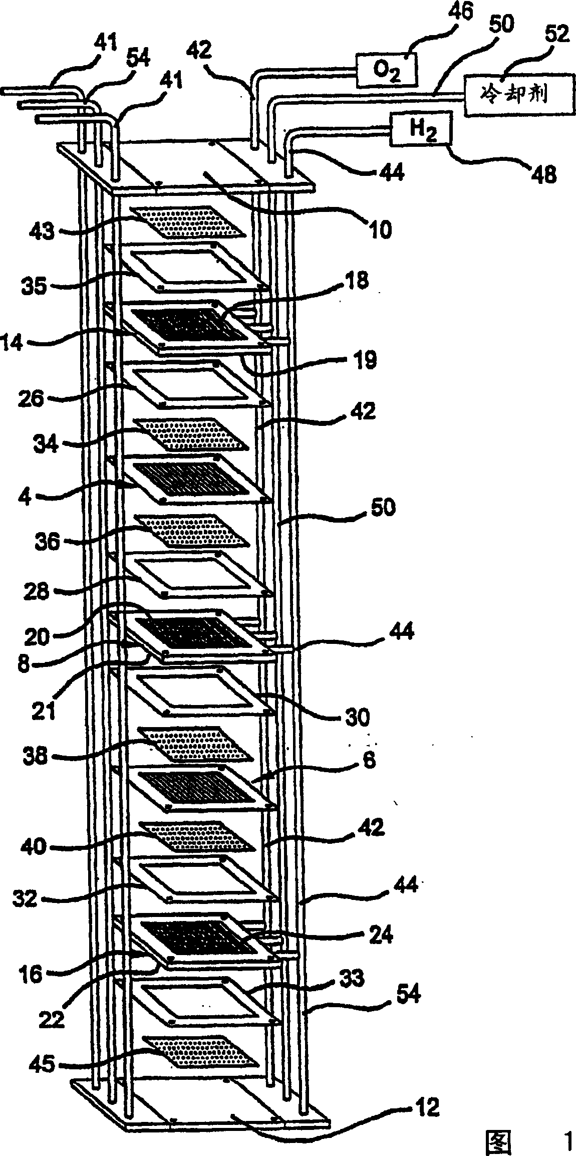
[0016] Figure 1 depicts two individual proton exchange membrane (PEM) fuel cells connected to form a stack with a pair of membrane electrode assemblies (MEAs) 4 and 6 sepa...


PUM

PropertyMeasurementUnit
thicknessaaaaaaaaaa
thicknessaaaaaaaaaa

Abstract

The present invention relates to an electrochemical cell having a terminal collector plate element that conducts electrical current from the stack. The terminal plate has an electrically conductive region and an electrically non-conductive region of the surface. The non-conductive region is coated with a corrosion resistant coating that comprises either a passivation layer, a corrosion-resistant polymeric layer, or both. Optionally, the conductive region of the terminal plate may be protected from oxidation, by coating with an oxidation-resistant metal layer. The oxidation-resistant layer may be further coated with a conductive oxidation-resistant polymeric layer. Other preferred aspects of the present invention include methods of treating the terminal plate to resist corrosion and oxidation while still maintaining electrical conductivity.

Description

technical field [0001] The present invention relates to proton exchange membrane fuel cells, and more particularly to corrosion resistant terminal current collector plates and methods of making the same. Background technique [0002] Fuel cells are proposed as power sources for electric vehicles or other uses. One of the known fuel cells is the PEM (i.e. Proton Exchange Membrane) fuel cell, comprising a so-called "membrane electrode assembly" comprising a thin solid polymer membrane electrolyte with the anode in one of the membrane electrolytes. The cathode is located on the other side of the membrane opposite the electrolyte. The anode and cathode typically include finely divided carbon particles, very finely divided catalyst particles attached to the inner and outer surfaces of the carbon particles, and a proton-conducting substance mixed with the catalyst and carbon particles. [0003] The membrane electrode assembly is sandwiched between a pair of electrically conducti...

Claims


Application Information

Patent Timeline
Patent Type & Authority Applications(China)
IPC IPC(8): H01R12/04H01R12/32H01MH01M8/00H01M8/02H01R3/08H01R12/55
CPCH01M8/0247Y02E60/50H01M8/0226H01M8/0228H01M8/0221H01M8/0206
Inventor B·K·布拉迪B·索姆帕利
Owner GENERAL MOTORS COMPANY
Why Eureka
Try Eureka