Polymer thermomechanical property testing device

A testing device and polymer technology, applied in the field of polymers, can solve problems such as limiting the application of polymer materials

Inactive Publication Date: 2006-09-06
SHANGHAI INST OF OPTICS & FINE MECHANICS CHINESE ACAD OF SCI
View PDF0 Cites 15 Cited by
  • Summary
  • Abstract
  • Description
  • Claims
  • Application Information

AI Technical Summary

Problems solved by technology

Manufacturers provide general material parameters: expansion coefficient, elastic modulus, glass transition temperature, but these parameters are measured at room temperature, due to the viscoelasticity and thermal stability of polymer materials, these parameters do not change linearly, so for Under other temperature and pressure conditions, the thermomechanical properties of polymer materials have not been given, which limits the application of polymer materials to a large extent.

Method used


Image

  • Polymer thermomechanical property testing device
  • Polymer thermomechanical property testing device
  • Polymer thermomechanical property testing device

Examples


Embodiment 1

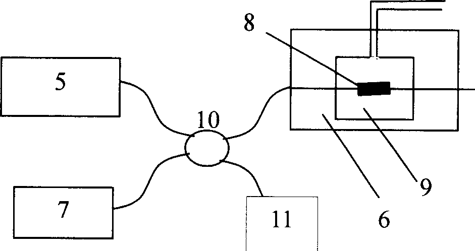
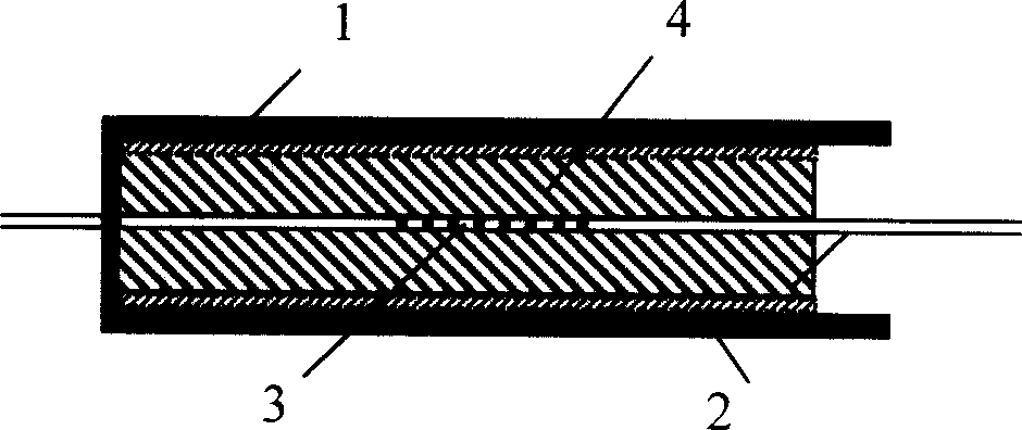
[0017] First, a polymer 4 to be tested is selected to pot the fiber grating sensor 3. During the potting process, the metal casing 1 is first inclined, and then the liquid of the polymer 4 is slowly injected along the metal casing 1, and the fiber grating sensor 3 is packaged in the metal casing 1, and finally the polymer 4 is heated and solidified to form a measuring piece 8, such as figure 2 shown. The measuring piece 8 is placed in the hydraulic device 9, and then the hydraulic device 9 is placed in a temperature control box 6, so as to apply temperature and pressure to it at the same time. The light emitted by the broadband light source (BBS) 5 enters the fiber grating sensor 3 through the 3dB coupler 10, and after being reflected, it is sent to the wavelength demodulation device 7 through the 3dB coupler 10, and the fiber grating sensor 3 is observed through the wavelength demodulation device 7 The change of reflection peak center wavelength Δλc and bandwidth Δλ 3dB . ...


PUM


Abstract

This device is made up of a measure part, a hydraulic pressure device, a controlled heat box, and the matching liquid. This invention can achieve measurement to polymerí»s heat expand coefficient, vitrification change, heat solidify form change, and springiness change, and thereby has wide application as high sensitivity and well repeatability.

Description

technical field [0001] The invention relates to polymers, in particular to a testing device for polymer thermomechanical properties. Background technique [0002] When polymer materials vary in a wide range of temperature and pressure, the thermomechanical properties of the polymer, such as expansion coefficient, elastic modulus, glass transition temperature and other important parameters determine its applicable range. Manufacturers provide general material parameters: expansion coefficient, elastic modulus, glass transition temperature, but these parameters are measured at room temperature, due to the viscoelasticity and thermal stability of polymer materials, these parameters do not change linearly, so for Under other temperature and pressure conditions, the thermomechanical properties of polymer materials have not been given, which limits the application of polymer materials to a large extent. In many actual engineering environments, the range of temperature and pressur...

Claims


Application Information

Patent Timeline
Patent Type & Authority Applications(China)
IPC IPC(8): G01N3/18G01N25/16
Inventor 孙安陈柏陈嘉琳林尊琪
Owner SHANGHAI INST OF OPTICS & FINE MECHANICS CHINESE ACAD OF SCI
Why Eureka
Try Eureka