Mask, method of manufacturing mask, device for manufacturing mask, method of manufacturing layer of luminescent material

A manufacturing method and mask technology, which are applied in the fields of original components for photomechanical processing, semiconductor/solid-state device manufacturing, optics, etc., can solve the problems of platform device complexity, mask temperature rise, position deviation, etc., and achieve suppression of masking. Effect of film failure, warping or warpage suppression

Active Publication Date: 2006-09-06
INTELLECTUAL KEYSTONE TECH LLC
View PDF1 Cites 4 Cited by
  • Summary
  • Abstract
  • Description
  • Claims
  • Application Information

AI Technical Summary

Problems solved by technology

However, in order to irradiate light from the bottom of the stage device, there is a problem that the stage device is complicated and enlarged. In addition, if the base material and the mask plate are moved and light is irradiated from the base material side, there is a problem that due to photocurable adhesion The agent is not cured, so the position of the base material and the mask plate deviates from the problem
[0005] In addition, even in the case of using a mask strengthened by joining the mask plate and the base material, the temperature of the mask rises during the vapor deposition process of the luminescent material, and the thermal expansion of the mask causes the through-hole The position deviation, resulting in the problem of unacceptable deviation of the thin film pattern

Method used


Image

  • Mask, method of manufacturing mask, device for manufacturing mask, method of manufacturing layer of luminescent material
  • Mask, method of manufacturing mask, device for manufacturing mask, method of manufacturing layer of luminescent material
  • Mask, method of manufacturing mask, device for manufacturing mask, method of manufacturing layer of luminescent material

Examples


Embodiment Construction

[0045] Hereinafter, embodiments of a mask manufacturing method, a mask manufacturing apparatus, a light emitting material film forming method, an electro-optical device, and an electronic device according to the present invention will be described with reference to the drawings.

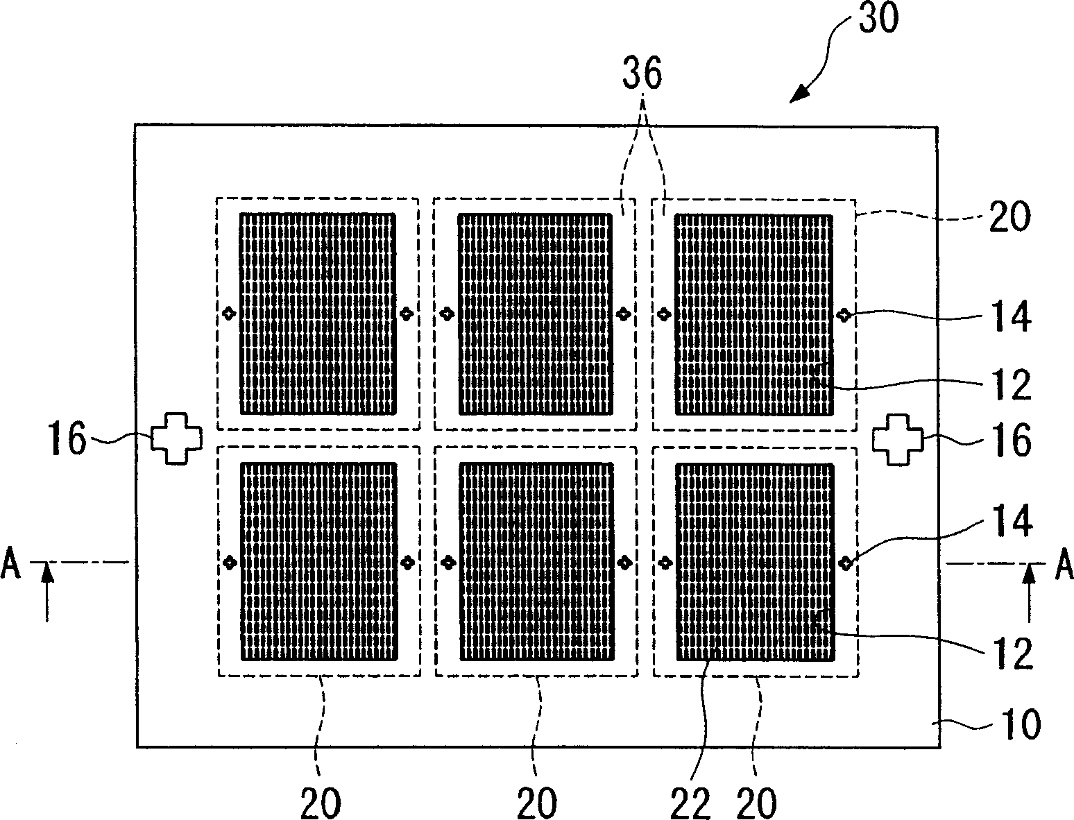
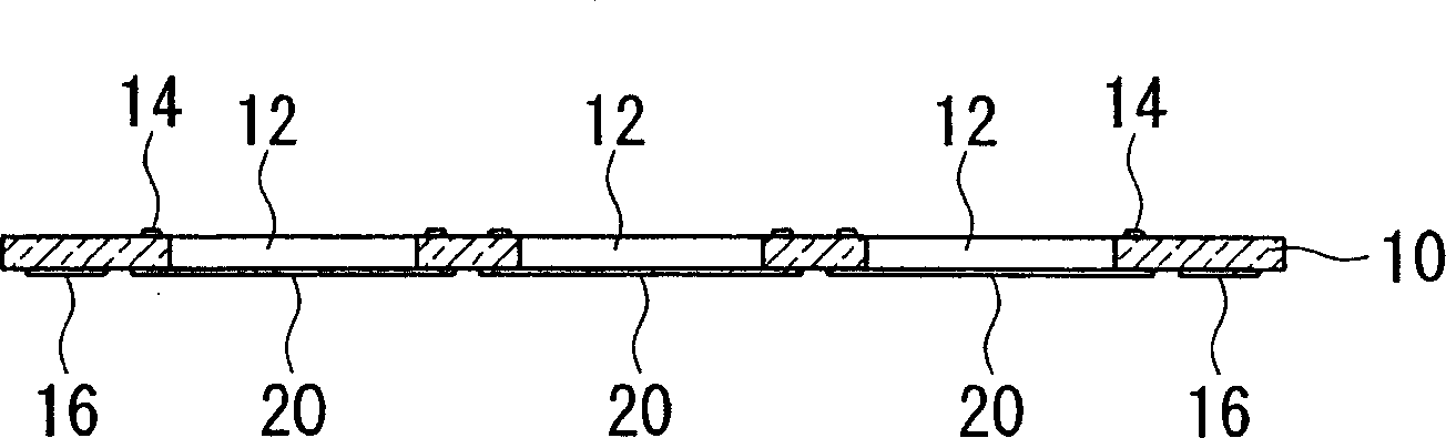
[0046] Figure 1A and Figure 1B is a diagram showing the mask 30 . Figure 1B yes Figure 1A The A-A line profile in.

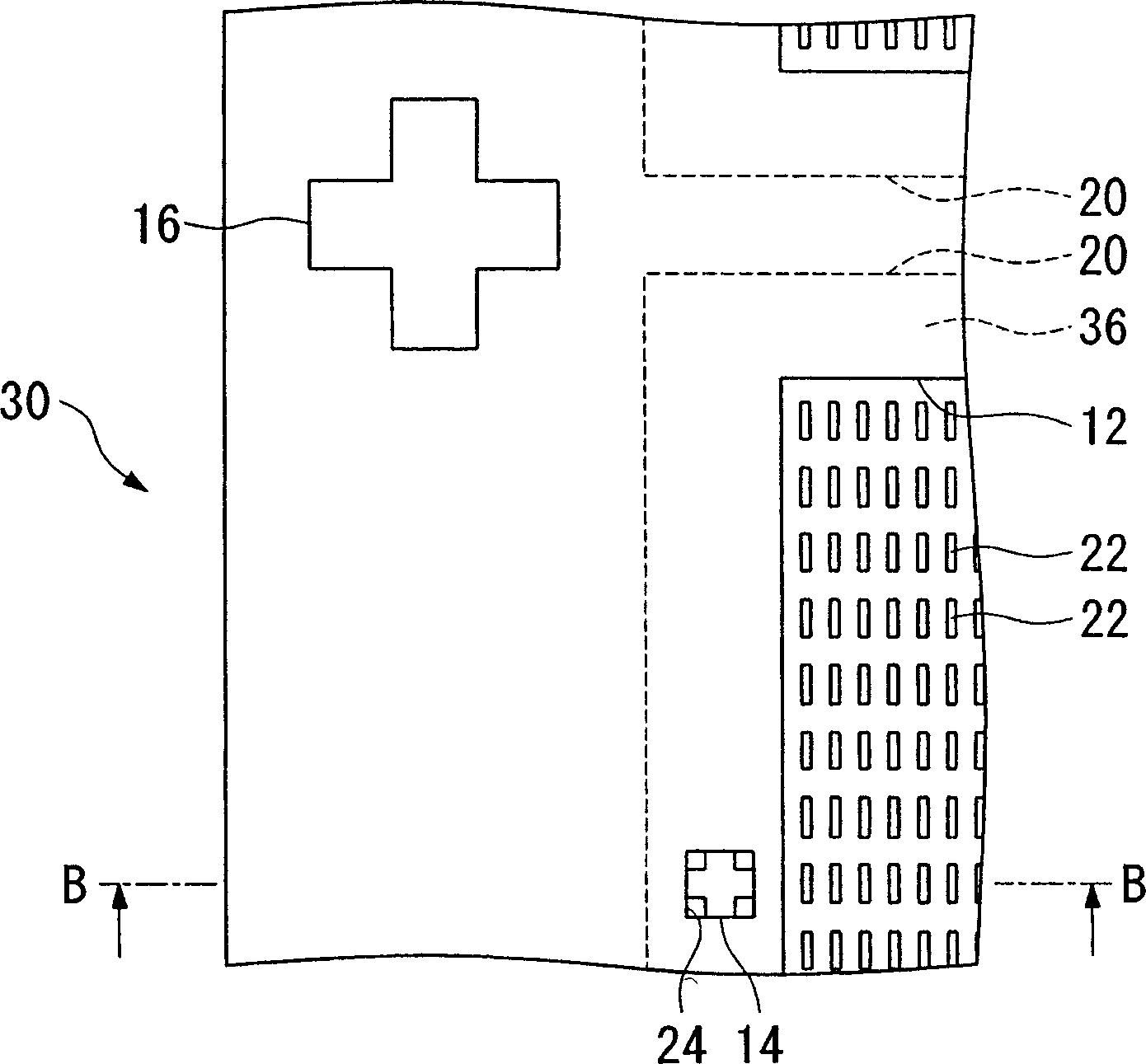
[0047] Figure 2A and Figure 2B It is an enlarged view showing the bonding region 36 of the mask 30 . Figure 2B yes Figure 2A B-B line profile.

[0048] The mask 30 used in the embodiment of the present invention is composed of a base material 10 and six mask members. Six openings 12 are formed in the base material 10 , corresponding to one opening 12 , and one mask member 20 is arranged so as to cover the opening 12 . That is, the region where the end portion of the mask member 20 overlaps with the end portion of the opening 12 of the base material 10 is used as the bond...


PUM


Abstract

This mask includes: a substrate in which an aperture is formed; a mask member which, along with being formed with a plurality of through holes, is joined to the substrate in correspondence to the aperture; and spacers which hold the substrate and the mask member with a predetermined gap between them.

Description

technical field [0001] The present invention relates to a mask used in a vapor deposition method and the like, a manufacturing method thereof, a manufacturing device, an electro-optical device, an electronic device, and the like. Background technique [0002] As a self-luminous display that makes a display device thinner than a liquid crystal display, an organic EL (electro luminescence electroluminescence) element (a light-emitting element with a light-emitting layer composed of an organic substance provided between the anode and the cathode) is used. An organic EL display is attracting attention as a next-generation technology. Low-molecular-weight organic materials and high-molecular-weight organic materials are known as light-emitting layer materials of organic EL devices, and the light-emitting layer composed of low-molecular-weight organic materials is formed by vapor deposition. When forming a film-emitting layer by vapor deposition, use a mask plate (a mask plate wi...

Claims


Application Information

Patent Timeline
Patent Type & Authority Applications(China)
IPC IPC(8): G03F1/00H01L21/027
Inventor 中楯真
Owner INTELLECTUAL KEYSTONE TECH LLC
Why Eureka
Try Eureka