Rotary expansion machine and fluid machinery

An expander and rotary technology, applied in the field of expander and fluid machinery, can solve the problems of large vibration and noise, pipeline fluid pulsation, pipeline damage, etc.

Inactive Publication Date: 2006-09-13
DAIKIN IND LTD
View PDF1 Cites 9 Cited by
  • Summary
  • Abstract
  • Description
  • Claims
  • Application Information

AI Technical Summary

Problems solved by technology

Therefore, there is a problem that the pulsation of the fluid occurs in the piping connected to the rotary expander, causing vibration and noise
In particular, there is a problem that when a liquid high-pressure f...

Method used


Image

  • Rotary expansion machine and fluid machinery
  • Rotary expansion machine and fluid machinery
  • Rotary expansion machine and fluid machinery

Examples


no. 1 Embodiment

[0064] A first embodiment of the present invention will be described. The air conditioner 10 of this embodiment includes the rotary expander according to the present invention.

[0065]

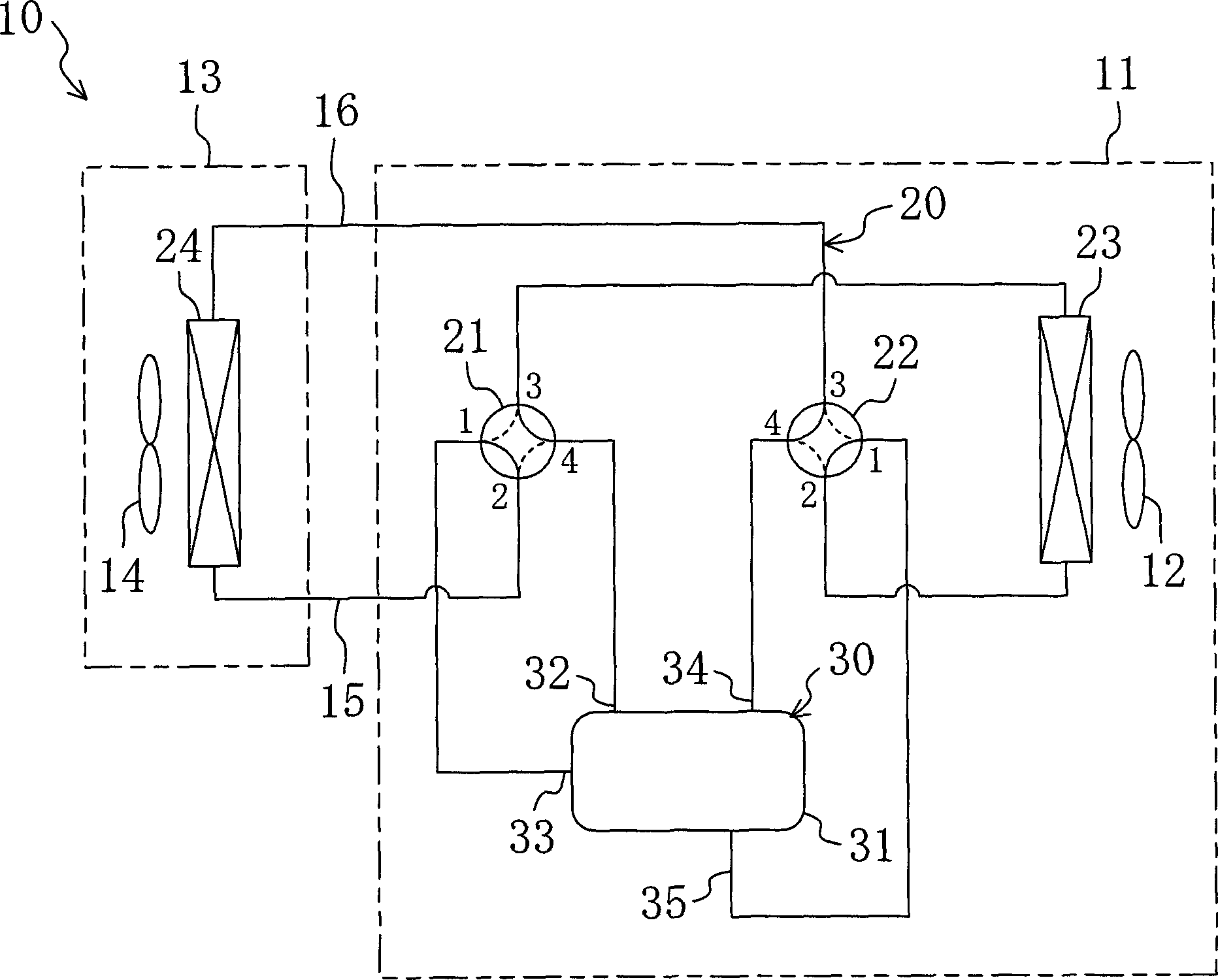
[0066] Such as figure 1 As shown, the above-mentioned air conditioner 10 is a so-called separate type air conditioner including an outdoor unit 11 and an indoor unit 13 . The outdoor fan 12 , the outdoor heat exchanger 23 , the first four-way switching valve 21 , the second four-way switching valve 22 , and the compression / expansion unit 30 are housed in the outdoor unit 11 . The indoor fan 14 and the indoor heat exchanger 24 are accommodated in the indoor unit 13 . The outdoor unit 11 is installed outdoors, and the indoor unit 13 is installed indoors. And, the outdoor unit 11 and the indoor unit 13 are connected together by a pair of connection pipes 15 , 16 . Note that details of the compression / expansion unit 30 will be described later.

[0067] The refrigerant circuit 20 is provide...

no. 3 Embodiment

[0129] A third embodiment of the present invention will be described. This embodiment is an example in which the configuration of the expansion mechanism unit 60 is changed from the first embodiment described above. Specifically, the expansion mechanism unit 60 of the first embodiment described above is constituted by an oscillating piston type fluid machine, whereas the expansion mechanism unit 60 of this embodiment is constituted by a rolling piston type fluid machine. Here, differences between the expansion mechanism unit 60 of this embodiment and the first embodiment described above will be described.

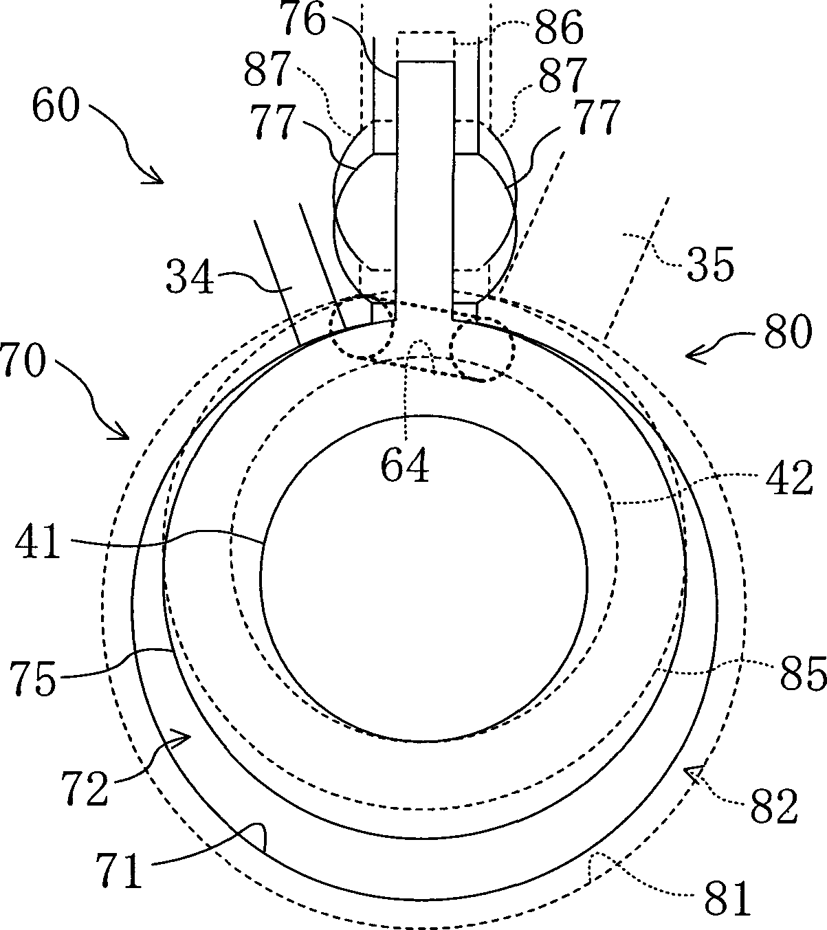
[0130] Such as Figure 10 As shown, the blades 76, 86 and the pistons 75, 85 are not integrally formed in each of the rotating mechanism parts 70, 80 of this embodiment. That is, each of the pistons 75 and 85 in this embodiment is formed into a simple ring shape or a cylindrical shape. In addition, one vane groove 78, 88 is formed in each housing 71, 81 of this embodimen...

no. 4 Embodiment

[0133] A fourth embodiment of the present invention will be described. This embodiment is an example in which the configuration of the expansion mechanism unit 60 is changed from the first embodiment described above. Here, differences between the expansion mechanism unit 60 of this embodiment and the first embodiment described above will be described.

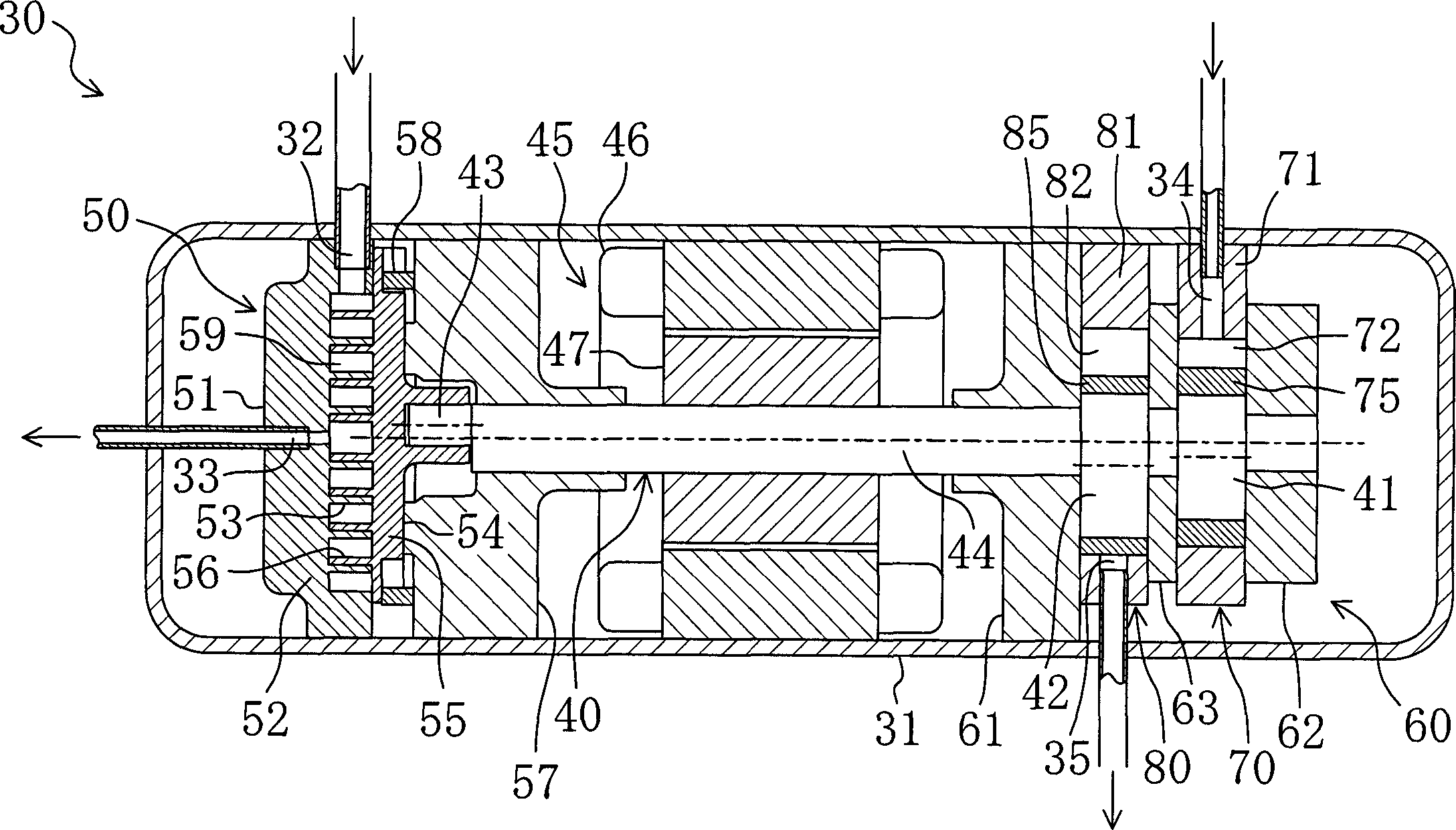
[0134] Such as Figure 11 As shown, in the expansion mechanism part 60 of this embodiment, the first rotation mechanism part 70 is arranged close to the motor 45 , and the second rotation mechanism part 80 is arranged farther from the motor 45 .

[0135] Specifically, in the expansion mechanism part 60, from Figure 11 The state in which the front head 61, the first shell 71, the middle plate 63, the second shell 81, and the back head 62 are stacked in order from the left to the right. In this state, the left end surface of the first housing 71 is closed by the front head 61 , and the right end surface is closed by the inter...


PUM


Abstract

The invention discloses a rotary type expander and a fluid machinery. The rotary type expander (60) is provided with two rotary mechanism parts (70, 80). These two rotary mechanism parts (70, 80) differ from each other in displacement volume. The outflow side of the first rotary mechanism part (70) of small displacement volume is fluidly connected to the inflow side of the second rotary mechanism part (80) of large displacement volume. In addition, the process in which the volume of a first low-pressure chamber (74) in the first rotary mechanism part (70) decreases is in synch with the process in which the volume of a second high-pressure chamber (83) in the second rotary mechanism part (80) increases. Refrigerant at high pressure is first introduced into a first high-pressure chamber (73) of the first rotary mechanism part (70). Thereafter, this high-pressure refrigerant passes through a communicating passage (64) and then flows by way of the first low-pressure chamber (74) into the second high-pressure chamber (83) while expanding. The after-expansion refrigerant flows out to an outflow port (35) from a second low-pressure chamber (84) of the second rotary mechanism part (80).

Description

technical field [0001] The present invention relates to an expander generating power by expansion of a high-pressure fluid and a fluid machine having the expander. Background technique [0002] Conventionally, a so-called rotary fluid machine has been known and widely used as a compressor for compressing a refrigerant in a refrigeration device. On the other hand, in the refrigerating apparatus disclosed in JP-A-2000-234814, an expander as an expansion mechanism is provided in a refrigerant circuit, and power recovery is performed from a refrigerant that is a high-pressure fluid in a supercritical state. The above-mentioned rotary fluid machine can also be used as such an expander for power recovery. At this time, the high-pressure fluid can be introduced into the rotary fluid machine as the expander, and the power can be obtained through the expansion of the high-pressure fluid. The power thus recovered in the expander is used to drive the compressor. [0003] The operati...

Claims


Application Information

Patent Timeline
IPC IPC(8): F01C1/32F01C1/356F01C11/00F01C13/04
Inventor 冈本昌和森脇道雄熊仓英二冈本哲也鉾谷克己
Owner DAIKIN IND LTD
Why Eureka
Try Eureka