
Piezoelectric resonator element and method of manufacturing same
A technology of piezoelectric resonance and components, which is applied in the manufacture/assembly of electrical components, piezoelectric/electrostrictive devices, piezoelectric devices/electrostrictive devices, etc., can solve the problem of FBAR and filter yield reduction, FBAR mechanical Intensity deterioration, filter electrical characteristics deterioration and other problems, to achieve the effect of preventing cracks and improving yield
- Summary
- Abstract
- Description
- Claims
- Application Information
AI Technical Summary
Problems solved by technology
Method used
Image

Examples
no. 1 approach
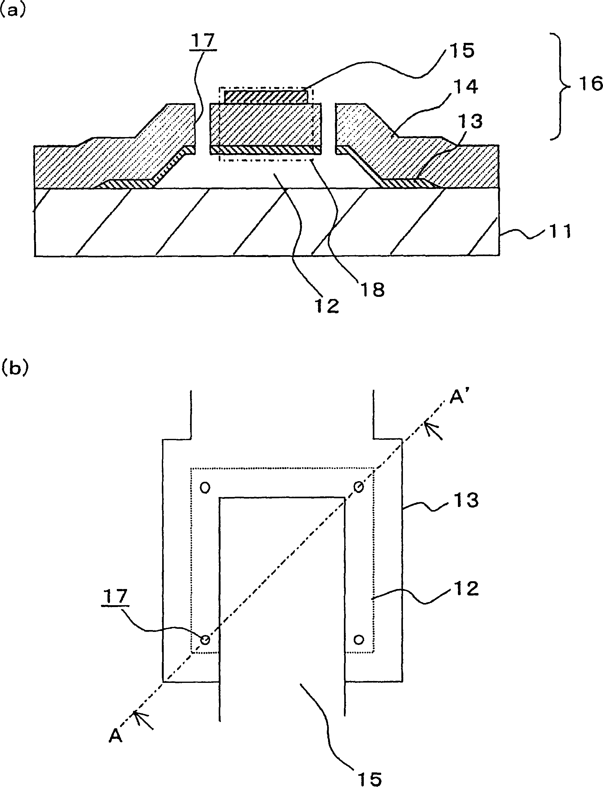
[0033]In the present example, as an example of an embodiment of the first piezoelectric resonant element of the present invention, the pass frequency range will be described using an example of FBAR at 2 GHz. figure 1 (a) represents a sectional view, figure 1 (b) represents a floor plan, figure 1 (a) is figure 1 (b) A-A' line profile. In addition, the same code|symbol is attached|subjected to the same structure as demonstrated in background art, and it demonstrates.
[0034] Such as figure 1 As shown in (a), a structure 16 is provided on a substrate 11 made of high-resistance silicon or high-resistance gallium arsenide. In this structure 16, a lower electrode 13 and a piezoelectric body are sequentially formed with an air layer 12 in between. layer 14 and upper electrode 15.
[0035] The lower electrode 13 is provided with a thickness of 0.1 μm to 0.5 μm while covering the air layer 12 and extending in one direction on the substrate 11 (see figure 1 (b)). Examples...
Embodiment 1~10
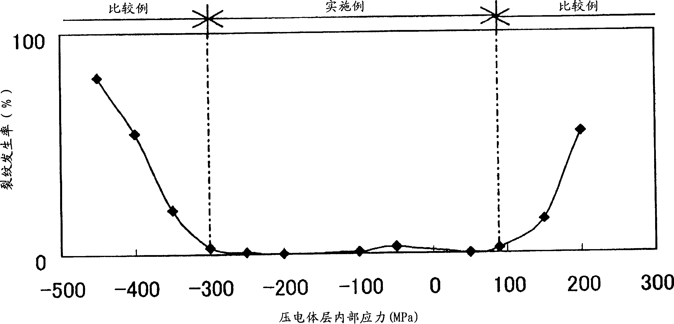
[0054] Such as figure 1 As shown, a plurality of FBARs of Examples 1 to 10 in which the internal stress of the piezoelectric layer 14 was varied within a range of not less than -300 MPa and not more than 90 MPa were produced by the same method as the example. Table 1 shows the internal stress of the piezoelectric layer 14 in each manufactured FBAR. The internal stress of the piezoelectric layer 14 was measured by the amount of warpage of the substrate 11 that occurred when the piezoelectric layer 14 made of an AlN film was formed on the substrate 11 provided with the lower electrode 13 .
[0055] Example 1
PUM
| Property | Measurement | Unit |
|---|---|---|
| Stress | aaaaa | aaaaa |
| Stress | aaaaa | aaaaa |
Abstract
Description
Claims
Application Information