
Thunderbolt protection device of wind turbine blade

A wind turbine blade and lightning protection technology, applied in the field of wind turbine blades, can solve the problems of reduced reliability of lightning protection and achieve high-strength effects

Active Publication Date: 2006-09-27
VESTAS WIND SYST AS
View PDF1 Cites 20 Cited by
  • Summary
  • Abstract
  • Description
  • Claims
  • Application Information

AI Technical Summary

Problems solved by technology

[0008] Another problem is that the lightning energy vaporizes the aluminum at the location of the lightning strike, resulting in less reliable lightning protection

Method used


Image

  • Thunderbolt protection device of wind turbine blade
  • Thunderbolt protection device of wind turbine blade
  • Thunderbolt protection device of wind turbine blade

Examples


Embodiment Construction

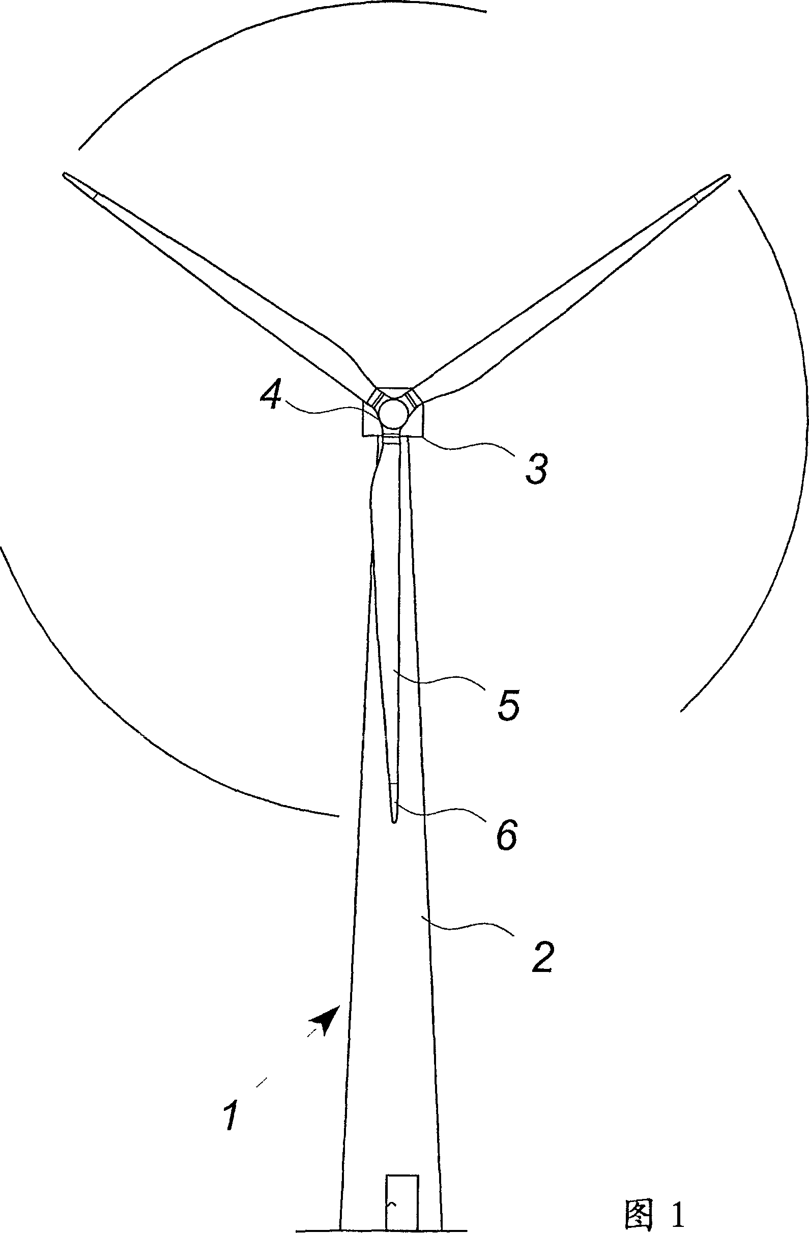
[0059] Figure 1 shows a modern wind turbine 1 with a tower 2 and a wind turbine nacelle 3 on top of the tower. A wind turbine rotor comprising three wind turbine blades 5 is connected to the nacelle by a low speed shaft extending out of the front of the nacelle. A tip 6 extends from the opposite end of the wind turbine blade.

[0060] As shown, wind above a certain level will actuate the rotor due to the lift created on the blades and cause the rotor to rotate in a direction perpendicular to the wind. This rotational movement is converted into electrical energy, which is supplied to the consumer grid.

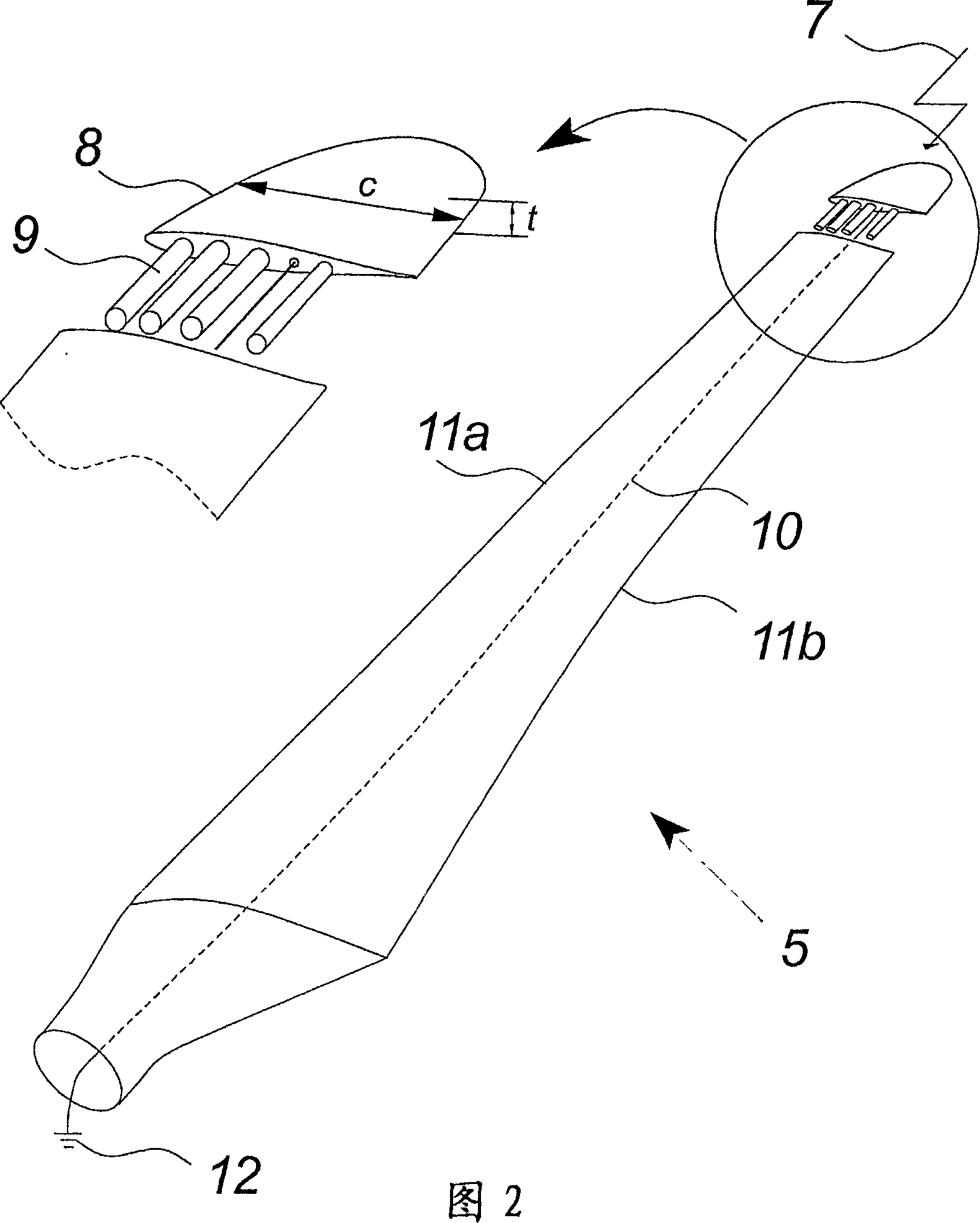
[0061] Figure 2 shows a wind turbine blade with a blade tip according to the invention, which is arranged next to the blade. The wind turbine blade may be any type of standard blade, for example a wind turbine blade made of composite material such as fiberglass.

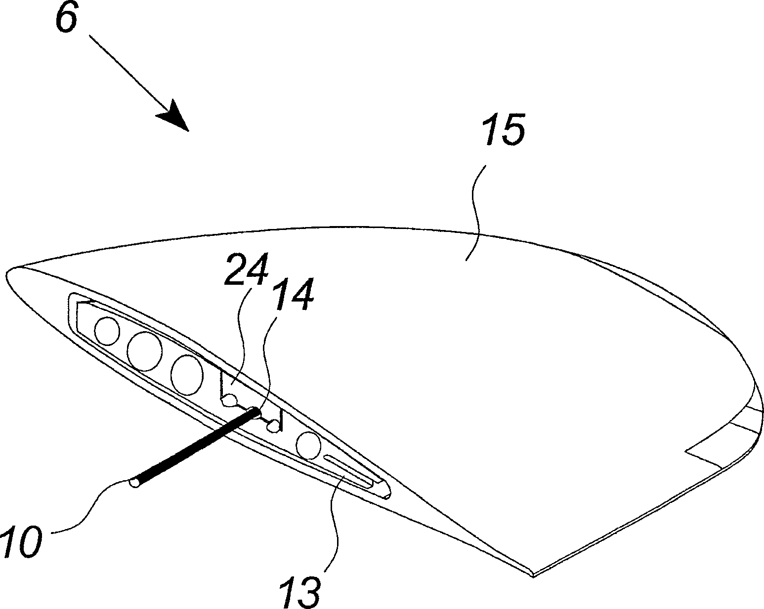
[0062] The blade tip almost corresponds in size and shape to a standard tip of a wind turbine blade and comprise...


PUM


Abstract

The invention relates to a wind turbine blade comprising lightning protection means. At least one section of the tip of said blade is made in solid metal and is included as part of said lightning means. The invention also relates to a wind turbine, a method of providing lightning receptor means to a wind turbine blade and use hereof.

Description

technical field [0001] The invention relates to a wind turbine blade according to the preamble of claim 1, a wind turbine according to the preamble of claim 31, a method of providing a wind turbine blade with a lightning receptor arrangement and the use of the method . Background technique [0002] Typically, wind turbines are erected in areas with favorable wind conditions such as suburban areas that include only a few tall obstacles such as trees or buildings. However, as wind turbines are erected with ever taller towers and rotor blades to make the most efficient use of the wind, and as wind turbines are the tallest objects in the area, there is a need to protect wind turbines from lightning strikes. [0003] Known lightning protection devices for wind turbines contain lightning receptors at the tip of each rotor blade in order to catch lightning strikes. The lightning is discharged to ground potential via down conductors in the blades and in the nacelle and tower. In ...

Claims


Application Information

Patent Timeline
Patent Type & Authority Applications(China)
IPC IPC(8): F03D11/00H02G13/00
CPCF05B2230/80F05B2280/1072Y02E10/722F03D11/00F03D11/0033F03D80/00F03D80/30F05B2240/307Y02E10/72Y02P70/50
Inventor P·希巴德C·克里斯坦森
Owner VESTAS WIND SYST AS
Learn More