
Cooling and heating system

A technology for cooling and heating and heating operation, which is applied in the field of cooling and heating systems, and can solve the problems of difficult heat exchanger and compressor capacity control, large performance coefficient, etc.

Inactive Publication Date: 2006-10-04
SANYO ELECTRIC CO LTD
View PDF1 Cites 10 Cited by
  • Summary
  • Abstract
  • Description
  • Claims
  • Application Information

AI Technical Summary

Problems solved by technology

Therefore, it is difficult to maximize the performance coefficient through the capacity control of the heat exchanger and compressor

Method used


Image

  • Cooling and heating system
  • Cooling and heating system
  • Cooling and heating system

Examples


Embodiment 1

[0041] In this example, refer to Figure 4 , 5 , 6 and 7 illustrate operation control using high pressure and evaporation temperature.

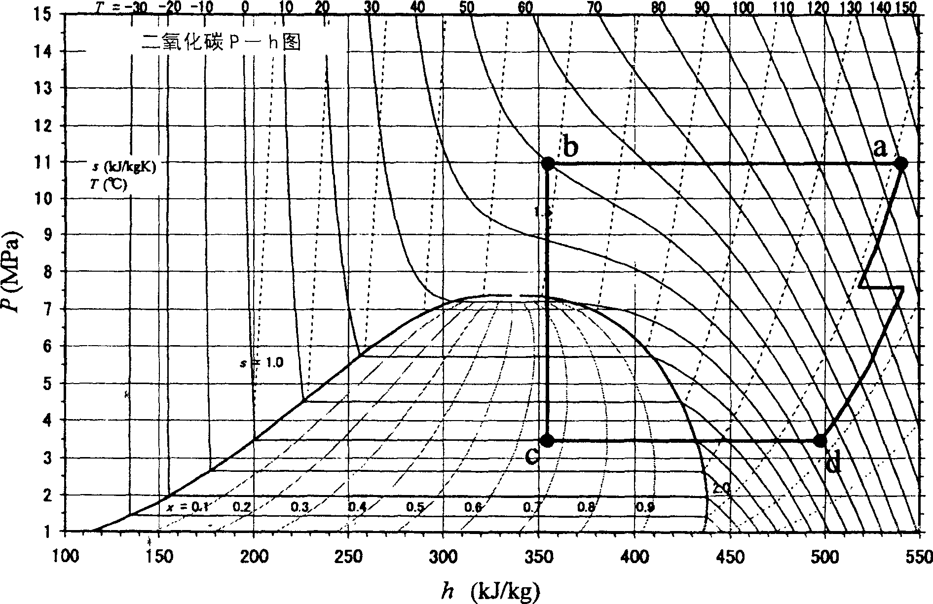
[0042] In this embodiment, first, if Figure 4 As shown in the heat load balance control flow (B1) of the heat load balance, detect the evaporation temperature T EVA (S150). The location to be detected varies depending on the operating state of the air-conditioning system 130, but in the figure 2 When the state c shown turns to state d, the temperature at which the refrigerant (carbon dioxide) changes from liquid to gas phase is the evaporation temperature T EVA . At this time, due to the intentional determination of the evaporation temperature T EVA and evaporation pressure P EVA , so the detection object can also be the evaporation pressure P EVA .

[0043] Next, detect the outlet refrigerant temperature T of the radiator GC (S152). Here, if in Figure 5 In the indoor unit 105a in the heating operation (S151), use the temperatu...

Embodiment 2

[0047] In this example, refer to Figure 8 , 9 , 10 and 11 describe the operation control according to the discharge temperature and the evaporation temperature.

[0048] In this embodiment, first, if Figure 8 As shown in the heat load balance control process (C1), the detection of the evaporation temperature T EVA (S250). The location to be detected varies depending on the operating state of the air-conditioning system 230, but in the figure 2 When the state c shown turns to state d, the temperature at which the refrigerant (carbon dioxide) changes from liquid to gas phase is the evaporation temperature T EVA . At this time, due to the intentional determination of the evaporation temperature T EVA and vapor pressure P EVA , so the detected object can also be the evaporation pressure PEVA .

[0049] Next, detect the outlet refrigerant temperature T of the radiator GC (S252). Here, if in Figure 9 In the indoor unit 205a in the heating operation (S251), use the tem...


PUM


Abstract

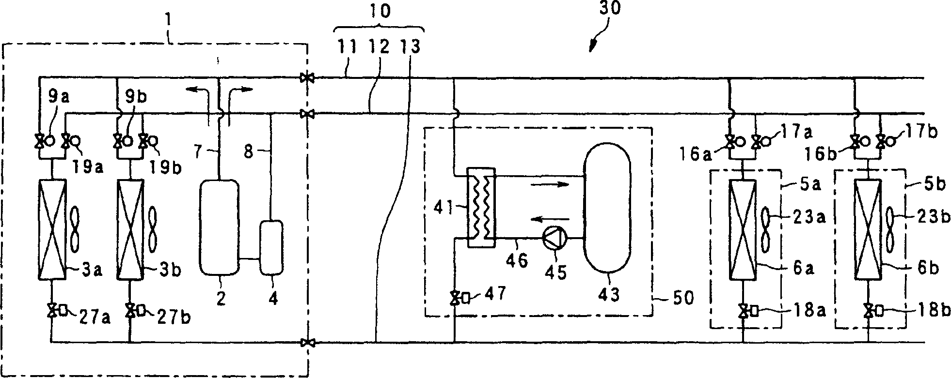
A cooling and heating system includes: an outdoor unit 101; a plurality of indoor units 105; a high pressure tube 111 ; a low pressure tube 112 ; and an intermediate tube 113 . The system includes: a refrigerant pressure detection unit PC01 for measuring a pressure of the refrigerant discharged from the compressor 102 ; a first refrigerant temperature detection unit TC03 which measures an outlet temperature of the refrigerant in a case where the outdoor heat exchanger 103 functions as a gas cooler and which measures an inlet temperature of the refrigerant in a case where the outdoor heat exchanger 103 functions as an evaporator; and a second refrigerant temperature detection unit TCO8 which measures an outlet temperature of the refrigerant in a case where the indoor heat exchanger 106 functions as a gas cooler and which measures an inlet temperature of the refrigerant in a case where the indoor heat exchanger 106 functions as an evaporator.

Description

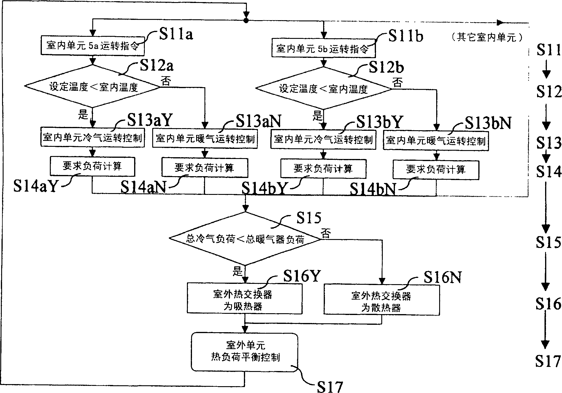
technical field [0001] The present invention relates to an air-conditioning system, and more particularly to an air-conditioning system capable of controlling the operating capacity so as to maximize the performance coefficient in an air-conditioning system using a refrigerant in a supercritical state. Background technique [0002] In an air-conditioning system using carbon dioxide refrigerant in a supercritical state, as an outdoor unit and a plurality of indoor units, it is possible to simultaneously perform cooling operation or heating operation of multiple indoor units, and it is possible to mix the cooling operation and heating operation. As a heating system, a device described in Patent Document 1 is known. Here, cooling refers to an operation performed when the set temperature of the indoor unit is lower than the indoor temperature, and heating refers to an operation performed when the set temperature of the indoor unit is higher than the indoor temperature. [0003]...

Claims


Application Information

Patent Timeline
Patent Type & Authority Applications(China)
IPC IPC(8): F25B29/00
CPCF25B2700/21152F25B2339/047F25B9/008F25B13/00Y02B30/741F25B2309/061F25B2313/0314F25B2600/17F25B2700/2117F25B2313/02791F25B2700/1931F25B2313/0231F25B2500/19F25B2600/0253F25B2313/0315Y02B30/70
Inventor 大竹雅久上村一朗向山洋佐藤晃司
Owner SANYO ELECTRIC CO LTD
Learn More