Gate driver circuit and display device having the same

A gate driver and circuit technology, applied to instruments, static memory, static indicators, etc., can solve the problems of gate driver circuit size increase and size increase, and achieve the effect of reducing area and size

Inactive Publication Date: 2006-10-04
SAMSUNG ELECTRONICS CO LTD
View PDF0 Cites 8 Cited by
  • Summary
  • Abstract
  • Description
  • Claims
  • Application Information

AI Technical Summary

Problems solved by technology

Furthermore, when the LCD panel includes two shift registers, the number of transistors forming stages is further increased, and thus, the size of a gate driver circuit including two shift registers increases as the number of transistors per stage increases.
Therefore, the LCD device must also increase in size to accommodate the gate driver circuit

Method used


Image

  • Gate driver circuit and display device having the same
  • Gate driver circuit and display device having the same
  • Gate driver circuit and display device having the same

Examples


Embodiment Construction

[0019] It should be understood that the exemplary embodiments of the invention described below may be varied in many different ways without departing from the inventive principles disclosed herein, and that, therefore, the scope of the invention is not limited to these specific embodiments below. Rather, these embodiments are provided by way of example, not limitation, so that this disclosure will be thorough and complete, and will fully convey the concept of the invention to those skilled in the art.

[0020] Hereinafter, embodiments of the present invention will be described by referring to the accompanying drawings. The same reference numerals denote the same elements throughout the drawings.

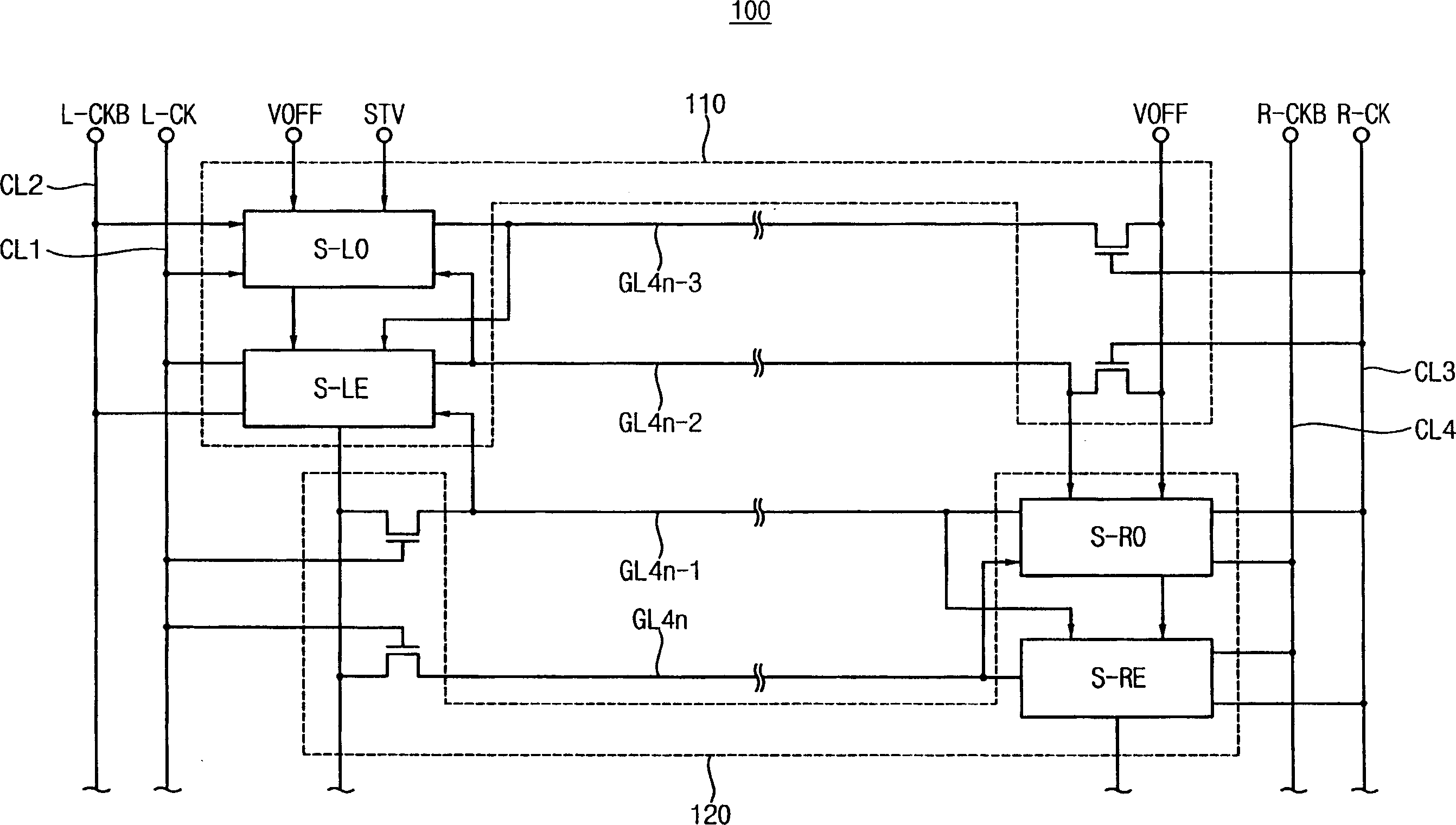
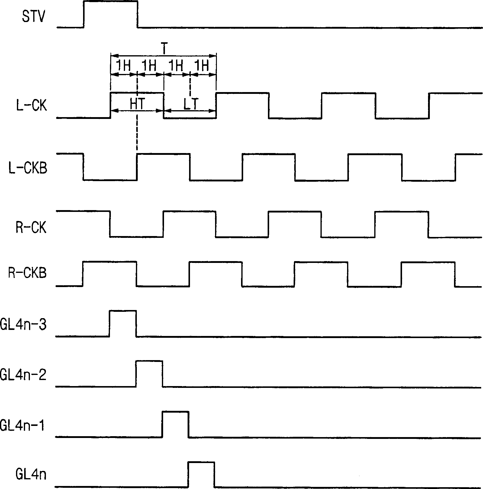
[0021] figure 1 To illustrate a block diagram of an exemplary embodiment of a gate driver circuit according to the present invention, and figure 2 for illustration figure 1 Timing diagram of the input and output of the gate driver circuit in .

[0022] refer to figure 1 , the g...


PUM


Abstract

A gate driver circuit includes a first shift register and a second shift register. The first shift register applies (4n-3)-th and (4n-2)-th gate signals to (4n-3)-th and (4n-2)-th gate lines, respectively, in response to a first clock signal, a second clock signal having a delayed phase by 1H time with respect to the first clock signal, and a third clock signal having opposite phase to the first clock signal. The second shift register applies (4n-1)-th and 4n-th gate signals to (4n-1)-th and 4n-th gate lines, respectively, in response to the first clock signal, the third clock signal, and a fourth clock signal having opposite phase to the second clock signal. Therefore, a number of transistors in the first and second shift registers may be reduced.

Description

technical field [0001] The present invention relates to a gate driver circuit and a display device having the gate driver circuit. More particularly, the present invention relates to a gate driver circuit capable of reducing its size, and a display device having the gate driver circuit. Background technique [0002] A liquid crystal display ("LCD") device includes an LCD panel. The LCD panel includes an array substrate, a color filter substrate facing the array substrate, and a liquid crystal layer interposed between the array substrate and the color filter substrate. The array substrate includes a plurality of gate lines for transmitting gate signals, and a plurality of data lines for transmitting data signals. The data lines intersect the gate lines and are insulated from the gate lines. [0003] The LCD device also includes a gate driver circuit that outputs a gate signal to the gate line, and a data driver circuit that outputs a data signal to the data line. Generall...

Claims


Application Information

Patent Timeline
Patent Type & Authority Applications(China)
IPC IPC(8): G09G3/36G09G3/20G02F1/133
CPCG11C19/287G09G3/3677G09G3/20B26B5/00B26B11/005
Inventor 朴商镇李明雨金炯杰鱼基汉郑东珍李柱亨
Owner SAMSUNG ELECTRONICS CO LTD
Why Eureka
Try Eureka