Nonaqueous electrolyte battery

A non-aqueous electrolyte and battery technology, applied in the direction of secondary batteries, battery electrodes, active material electrodes, etc., can solve the problems of low metal foil adhesion, battery voltage drop, peeling, etc.

Active Publication Date: 2006-10-04
SANYO ELECTRIC CO LTD
View PDF2 Cites 8 Cited by
  • Summary
  • Abstract
  • Description
  • Claims
  • Application Information

AI Technical Summary

Problems solved by technology

On the other hand, since olivine-type lithium phosphate has low adhesion to the metal foil as the positive electrode current collector, even if a binder is mixed, there is a problem of peeling off from the positive electrode current collector.
[0013] In this case, although it can be considered to reduce the thickness of the positive electrode mixture layer to suppress the method of peeling off the positive electrode active material from the positive electrode current collector, when the thickness of the positive electrode mixture layer is reduced, the positive electrode current collector will be in the positive electrode. The proportion of the thickness increases, so there is a problem that the volumetric energy density of the positive electrode decreases
In addition, since olivine-type lithium phosphate is different from the previously used LiCoO 2 , LiNiO 2 , Li x Ni 1-y co y o 2 , LiMn 2 o 4 and LiNi 1/3 co 1/3 mn 1/3 o

Method used


Image

  • Nonaqueous electrolyte battery
  • Nonaqueous electrolyte battery
  • Nonaqueous electrolyte battery

Examples


no. 1 Embodiment

[0084] (Example)

[0085] As an example, a positive electrode and a test battery were fabricated in the same manner as in the best mode for carrying out the invention.

[0086] Hereinafter, the positive electrode and the experimental battery thus fabricated are referred to as the positive electrode a of the present invention and the positive electrode of the present invention, respectively.

[0087] Battery A.

Embodiment 1

[0144] A battery was produced in the same manner as in Example 1 of the first example, except that a positive electrode was produced as follows.

[0145] Hereinafter, the battery produced in this way is referred to as the battery B1 of the present invention.

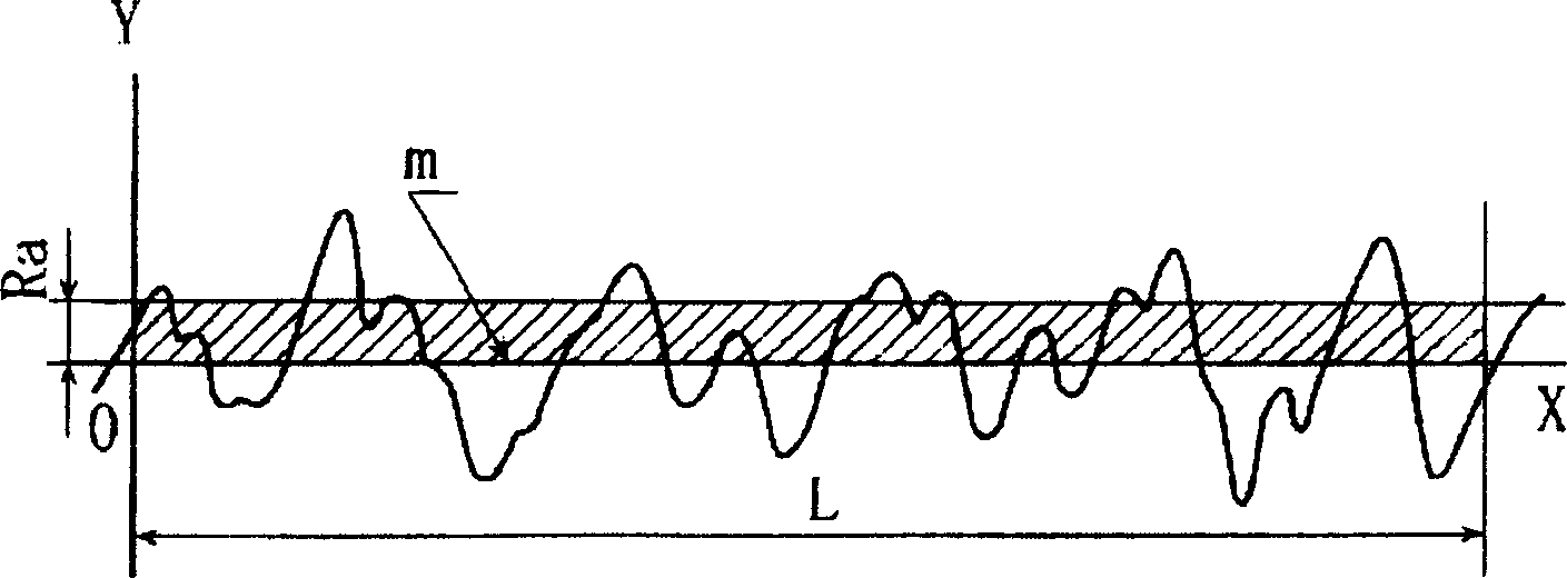
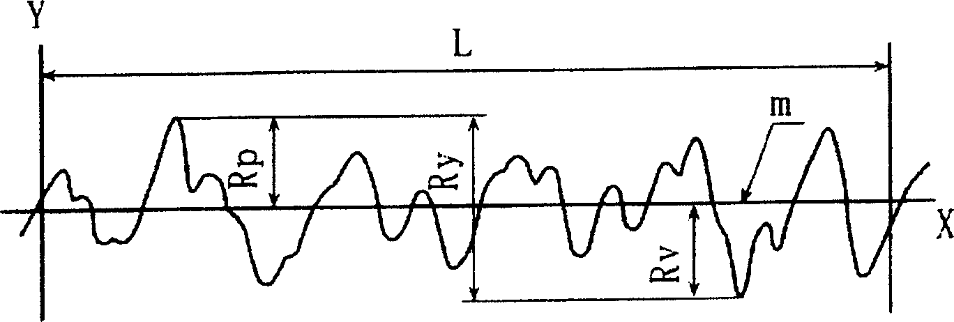
[0146] First, according to the lithium iron phosphate (LiFePO 4 ) reaches 85% by mass of the positive electrode active material containing layer as a whole, and carbon black (BET specific surface area: 70m 2 / g) was measured so that it might become 10 mass % of the whole positive electrode active material containing layer, and both were mixed. Then, to the mixture, polyacrylonitrile (PAN) was added as a binder to make it 5% by mass of the entire positive electrode active material-containing layer, and an appropriate amount of N-methylpyrrolidone (NMP) solution was added as a solvent. , made a slurry by mixing. Then, the slurry was applied to a surface with a surface roughness Ra of 0.14 μm (Ra=0.14 μm) and a maximum he...

Embodiment 2

[0163] Except for carbon black as a conductive agent, using a BET specific surface area of ​​39m 2 A test battery was produced in the same manner as in Example 1, except for the material used in the test example 1.

[0164] The battery produced in this way is hereinafter referred to as battery B2 of the present invention.


PUM

PropertyMeasurementUnit
Thicknessaaaaaaaaaa
Surface roughnessaaaaaaaaaa

Abstract

A non-aqueous battery with improved volume energy density and enhanced load characteristics is made available even when using olivine-type lithium phosphate as a positive electrode active material. The non-aqueous electrolyte battery of the present invention is provided with a positive electrode (1) containing lithium iron phosphate as a positive electrode active material, a negative electrode (2), and a non-aqueous electrolyte (4). In the positive electrode (1), a positive electrode active material-containing layer that is made of the positive electrode active material, a conductive agent, and a binder agent is formed on a positive electrode current collector. The positive electrode current collector has a thickness of less than 20 mum and its surface that is in contact with the positive electrode active material-containing layer has a mean surface roughness Ra of greater than 0.026 mum.

Description

technical field [0001] The present invention relates to a nonaqueous electrolyte battery comprising a positive electrode containing lithium iron phosphate as a positive electrode active material, a negative electrode, and a nonaqueous electrolyte, and particularly relates to improvement of a positive electrode current collector with improved adhesion to the positive electrode active material. Background technique [0002] In recent years, mobile information terminals such as mobile phones, personal computers, and PDAs have been rapidly reduced in size and weight, and further increases in capacity are required for batteries serving as driving power sources. Nonaqueous electrolyte secondary batteries represented by lithium ion secondary batteries are widely used as driving power sources for mobile information terminals as described above because of their high energy density and high capacity. [0003] The non-aqueous electrolyte secondary battery generally uses lithium cobalta...

Claims


Application Information

Patent Timeline
IPC IPC(8): H01M4/02H01M4/58H01M4/66H01M10/40
CPCY02E60/122Y02T10/7011Y02E60/10
Inventor 井上尊夫堂上和范虞有为藤本正久藤谷伸
Owner SANYO ELECTRIC CO LTD
Why Eureka
Try Eureka