Waste gas treatment device capable of simultaneously recovering waste heat and removing contaminant

A waste gas treatment device and waste gas treatment technology, which are applied in waste heat treatment, energy industry, climate sustainability, etc., can solve the problems of large investment and floor space, increase heat loss, and large exhaust gas flow resistance, and achieve investment savings. Effect

Inactive Publication Date: 2006-10-11
HUAZHONG UNIV OF SCI & TECH
View PDF0 Cites 12 Cited by
  • Summary
  • Abstract
  • Description
  • Claims
  • Application Information

AI Technical Summary

Problems solved by technology

The use of heat exchangers to preheat the air and the use of catalytic reduction reactors to remove pollutants in series not only requires a large investment and

Method used


Image

  • Waste gas treatment device capable of simultaneously recovering waste heat and removing contaminant
  • Waste gas treatment device capable of simultaneously recovering waste heat and removing contaminant
  • Waste gas treatment device capable of simultaneously recovering waste heat and removing contaminant

Examples


Example Embodiment

[0020] Example 1

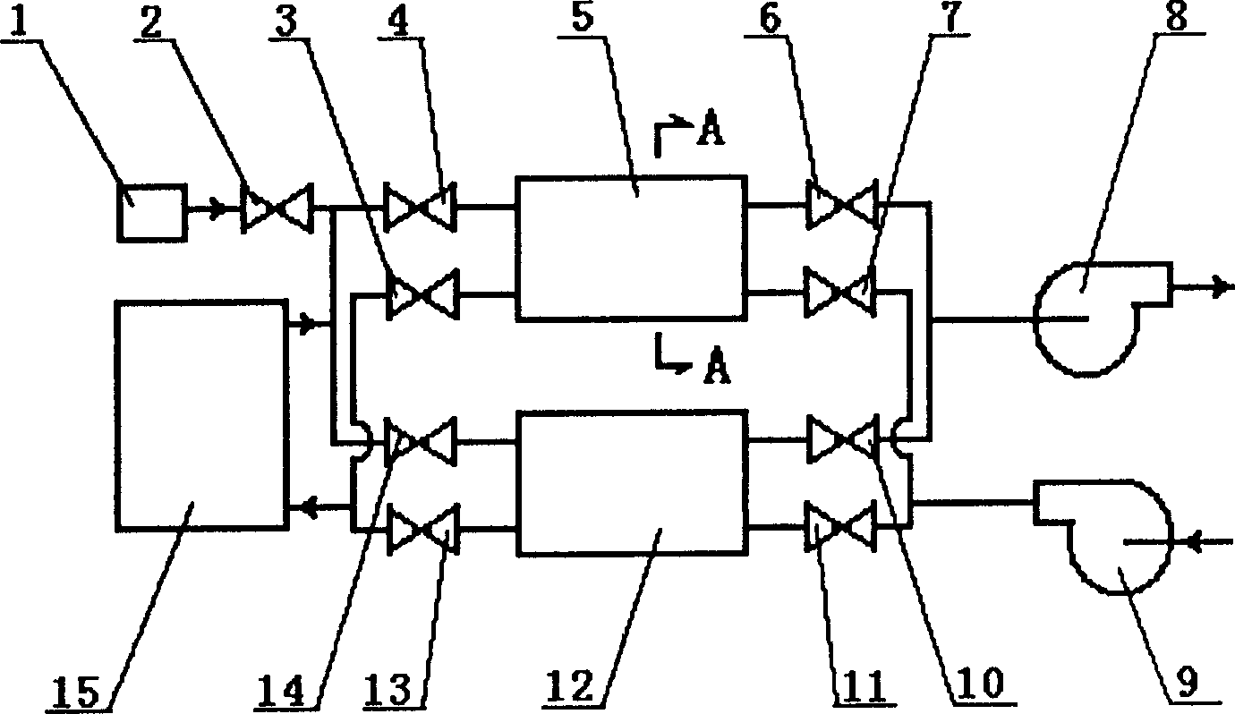
[0021] Depend on figure 1 , figure 2 and image 3 As shown, the present invention may include exhaust gas treatment unit, reducing agent NH 3 Storage tank 1, valve 2, industrial furnace 15, induced draft fan 8 and blower 9.

[0022] The structure of the waste gas treatment unit is that one end of the first porous ceramic regenerator 5 is connected to the inlet end of the first valve 3 and the outlet end of the second valve 4, and the other end of the first porous ceramic regenerator 5 is connected to the second valve 4. The inlet end of the third valve 6 is connected with the outlet end of the fourth valve 7, one end of the second porous ceramic regenerator 12 is connected with the inlet end of the fifth valve 13 and the outlet end of the sixth valve 14, and the second porous ceramic The other end of the heat storage chamber 12 is connected with the inlet end of the seventh valve 10 and the outlet end of the eighth valve 11; Covered with a redox cataly...

Example Embodiment

[0027] Example 2

[0028] Depend on Figure 4 shown, with figure 1 The difference is that: figure 1 The first valve 3 , the second valve 4 , the fifth valve 13 and the sixth valve 14 in the shown exhaust gas treatment unit are replaced by a first two-position four-way rotary valve 16 .

Example Embodiment

[0029] Example 3

[0030] Depend on Figure 5 shown, with figure 1 The difference is that: figure 1 The four valves of the third valve 6 , the fourth valve 7 , the seventh valve 10 and the eighth valve 11 in the shown exhaust gas treatment unit are replaced by a second two-position four-way rotary valve 17 .


PUM


Abstract

The invention discloses a waste gas processor which can recycle the left heat and remove contaminant. Wherein, said device comprises a waste gas treating unit, while one end of first porous ceramic heat accumulating room is connected to the inlet of first valve and the outlet of second valve; another end is connected to the inlet of third valve and the outlet of forth valve; one end of second porous ceramic heat accumulating room is connected to the inlet of fifth valve and the outlet of sixth valve, while another end is connected to the inlet of seventh valve and the outlet of eighth valve; the surface of inner wholes of first and second porous ceramic heat accumulating rooms are coated with oxidation-reduction catalyst. The invention can use the left heat of waste gas to preheat air, and remove the harmful gas of waste gas, to reduce cost and improve efficiency.

Description

technical field [0001] The invention relates to a waste gas treatment device, in particular to a device for recovering waste heat and removing pollutants from high-temperature waste gas discharged from boilers, industrial furnaces and refining and chemical devices. Background technique [0002] Energy saving and environmental protection are two major problems that need to be solved urgently in the national economic and social development of our country. Refining equipment and various heating furnaces in the petrochemical industry, thermal power plant boilers in the power industry, iron and steel metallurgy, building materials and various industries in the machinery industry Furnaces and kilns use a large amount of fossil fuels. During the production process, high-temperature flue gas containing a large amount of pollutants (especially sulfur oxides and nitrogen oxides) is often discharged into the air, which wastes energy and pollutes the environment. For this reason, variou...

Claims


Application Information

Patent Timeline
IPC IPC(8): F27D17/00
CPCY02P10/25Y02P80/15
Inventor 靳世平黄素逸王晓墨杜一庆龙妍明廷臻
Owner HUAZHONG UNIV OF SCI & TECH
Why Eureka
Try Eureka