Microstrip antenna array with high gain and wide angle field wave lobe

A microstrip antenna, wide-angle technology, used in antenna arrays, antennas, electrical components, etc., can solve problems such as inability to increase gain

Inactive Publication Date: 2006-10-11
INST OF MICROELECTRONICS CHINESE ACAD OF SCI
View PDF0 Cites 16 Cited by
  • Summary
  • Abstract
  • Description
  • Claims
  • Application Information

AI Technical Summary

Problems solved by technology

However, when this single-chip microstrip dielectric antenna array is used, the gain of the antenna array is higher than that of the microstrip dielectric unit in a certain field lobe range, but it cannot achieve a relatively uniform increase in gain on a wide-angle field lobe.

Method used


Image

  • Microstrip antenna array with high gain and wide angle field wave lobe
  • Microstrip antenna array with high gain and wide angle field wave lobe
  • Microstrip antenna array with high gain and wide angle field wave lobe

Examples


Embodiment Construction

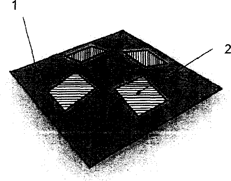
[0037] The invention discloses an antenna array with high gain and wide-angle field lobe that can be used for communication, navigation and positioning, which includes forming a microstrip dielectric antenna array on a polyhedral microstrip dielectric plate, passing through a signal power combiner Signals received by each microstrip antenna are combined. Its characteristic is that the polyhedral microstrip dielectric plate can be designed as any polyhedron with any angle to the bottom surface according to needs, so as to meet the requirements of high gain and wide field lobe.

[0038] see figure 1 , which is a schematic diagram of the shape of the microstrip antenna array of the present invention, that is, a tetrahedron cone as an example.

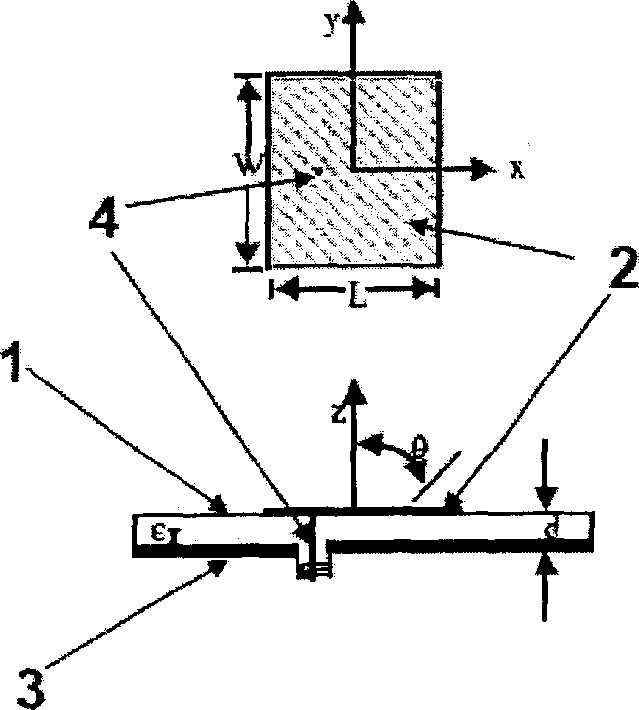
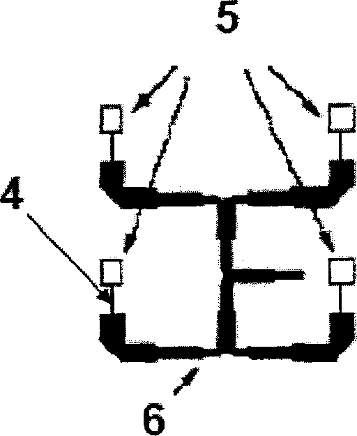
[0039] The antenna includes: a microstrip metal patch (2) on a polyhedral microstrip dielectric plate (1), a ground reflection surface (3) and a feeder line (4) to form a microstrip antenna unit (5), thereby further forming a polyhedron m...


PUM


Abstract

The related microstrip antenna with high gain and wide angle-field lobe comprises the microstrip metal paster (2) on polyhedral microstrip medium plate (1) included any angle with bottom for different requests, and the microstrip antenna unit (5) with grounding reflector (3) and feed line (4) to form further the polyhedral microstrip antenna array. With small size and cost, this portable product has wide application special the miniaturized satellite signal antenna.

Description

【Technical field】 [0001] The invention relates to the technical field of microstrip antennas for communication and navigation and positioning, in particular to a microstrip antenna array with high gain and wide-angle field lobe. 【Background technique】 [0002] In various satellite communication and navigation and positioning systems, single-chip microstrip dielectric antennas and microstrip antenna arrays formed on a dielectric plane plate composed of single-chip microstrip dielectric units have been widely used. However, when this single-chip microstrip dielectric antenna array is used, the gain of the antenna array is higher than that of the microstrip dielectric unit in a certain field lobe range, but it cannot achieve a relatively uniform increase in gain on a wide-angle field lobe. However, in satellite communication and navigation and positioning systems, it is required to have relatively consistent high-gain antennas in the wide-angle field lobe. The method to solve ...

Claims


Application Information

Patent Timeline
Patent Type & Authority Applications(China)
IPC IPC(8): H01Q21/00H01Q13/08
Inventor 阎跃鹏
Owner INST OF MICROELECTRONICS CHINESE ACAD OF SCI
Why Eureka
Try Eureka