Method for optimization of an order for component mounting and apparatus for optimization of an order for component mounting

An optimization method and component technology, applied in the direction of electrical components, electrical components, multi-objective optimization, etc., can solve problems such as long computing time, inability to flexibly handle changes in production line organization, and achieve reduction of takt time, easy re-optimization, and flexible processing. Effect

Active Publication Date: 2006-10-11
PANASONIC CORP
View PDF3 Cites 11 Cited by
  • Summary
  • Abstract
  • Description
  • Claims
  • Application Information

AI Technical Summary

Problems solved by technology

For this reason, when the types of components and the number of assembly points (which are the object of optimization) increase, there is a problem that it takes a long calculation time for optimization
[0007] In addition, when the number of assemblers on the assembly line is changed, since optimization must be performed again from the beginning, there is a problem that changes in the organization of the production line cannot be flexibly handled

Method used


Image

  • Method for optimization of an order for component mounting and apparatus for optimization of an order for component mounting
  • Method for optimization of an order for component mounting and apparatus for optimization of an order for component mounting
  • Method for optimization of an order for component mounting and apparatus for optimization of an order for component mounting

Examples


no. 1 example

[0059] Hereinafter, a component mounting system in a first embodiment of the present invention will be described with reference to the drawings.

[0060] (Component assembly system)

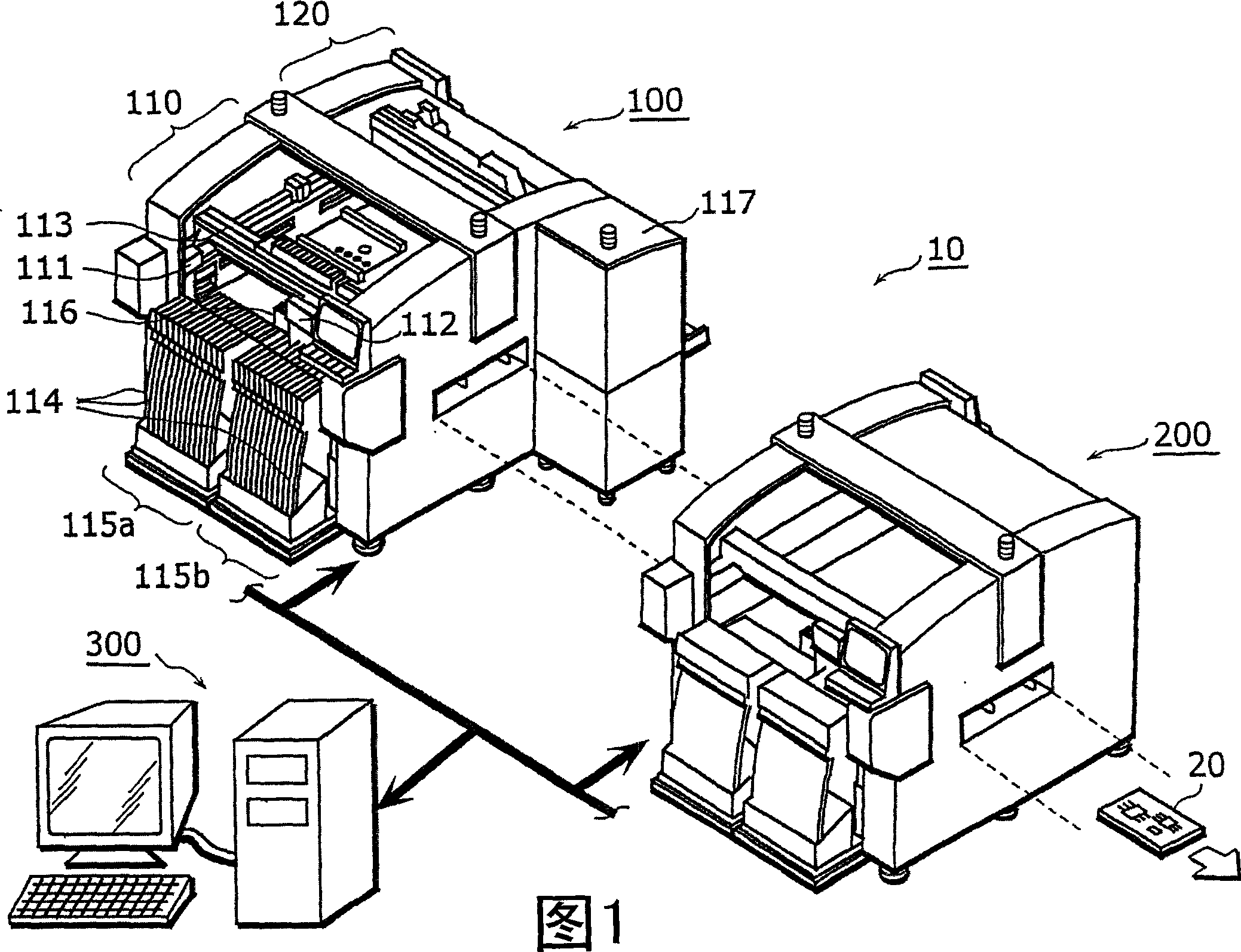
[0061] FIG. 1 is an external view showing the overall structure of a component mounting system 10 in the present invention. The assembly system 10 includes a plurality (here, two) of assemblers 100 and 200 , and an optimization device 300 . The assemblers 100 and 200 form a production line in which electronic components are assembled on a circuit board 20 conveyed downstream. The optimization device 300 optimizes the assembly sequence of the required electronic components according to information in, for example, multiple databases at the start of production, and the setting and control have been provided by information assembly of NC (Numeric Control, digital control) data generated by optimization devices 100 and 200.

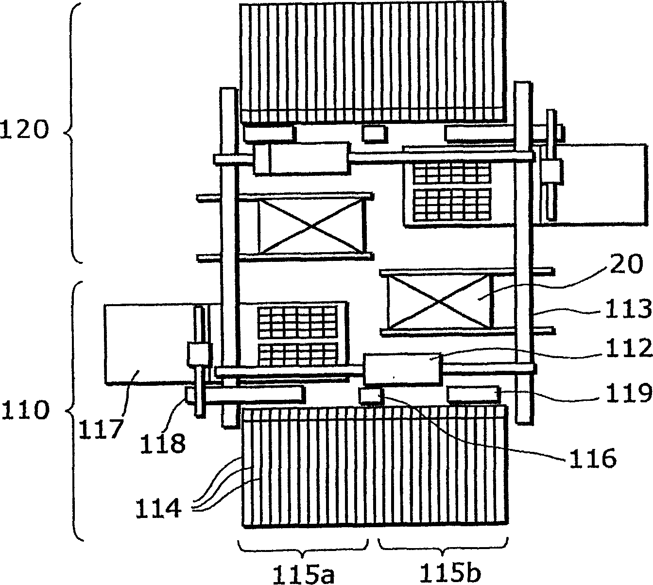
[0062] The assembler 100 is equipped with two subunits (a front terminal...

no. 2 example

[0160] Next, a component mounting system according to a second embodiment of the present invention will be explained.

[0161] The component mounting system according to the second embodiment has the same hardware structure as the component mounting system in the first embodiment. However, the assembler 100 in this embodiment is compatible with figure 2 Assembler 100 shown differs in that it does not include subunit 110 and subunit 120, instead it includes left subunit 410 and right subunit 420, as Figure 21 shown. To reduce the width of the space required for component assembly, the Figure 21 The center portion of the shown assembler is provided with reference pins for determining the position of the panels. The panel 20 enters from the right in the figure and is assembled with components through the right subunit 420 . Subsequently, the panel 20 is transferred to the left subunit 410 , and components are assembled by the left subunit 410 .

[0162] FIG. 22 is a flowc...


PUM


Abstract

The panel contains a plurality of patterns having the same component placement structure, and the plurality of patterns respectively correspond to a plurality of sub-panels obtained by dividing the above-mentioned panel. The method for optimizing the assembly order of components i) includes the step (S2) of optimizing the assembly order of components for any one of the plurality of patterns by dividing the total number of the patterns contained in the panel by the assembler to calculate the quotient and the remainder (S4), a step (S6) for determining the quotient as the number of patterns allocated when the remainder is zero, and a step (S6) for determining the quotient as the number of patterns allocated when the remainder is one or more ) determining the quotient plus 1 as the number of patterns assigned to the same number of assemblers as the remainder starting from the assembler most upstream of the processing position, and ii) determining the quotient as the number of patterns assigned to the remaining The number of patterns of the assembler (S6 to S10), and a step for assigning the assigned number of patterns to each assembler (S12).

Description

technical field [0001] The present invention relates to a method for optimizing the order in which components are assembled by an assembler. In particular, the present invention relates to a method of optimizing the order in which components are assembled on a panel comprising a plurality of patterns. Background technique [0002] A component assembling system in which a plurality of assemblers for assembling electronic components on panels (such as printed circuit boards) are provided in one assembly line, in which it is necessary to Takt times are consistent to keep the assembly line balanced. Conventionally, in such component assembly systems, the optimization of the assembly sequence is performed by allocating the components to be processed by each assembler according to the tact time and the number of components for assembly allocated to each component (for example, Official publication of Japanese Laid-Open Patent Application No. 09-18199 and No. 10-209697). [0003...

Claims


Application Information

Patent Timeline
Patent Type & Authority Applications(China)
IPC IPC(8): G05B19/18G06F17/50G06Q10/00H05K13/04
CPCG06Q10/06G06F30/00G06F2111/06H05K13/085Y10T29/4913G05B19/18H05K13/04
Inventor 前西康宏山崎琢也山崎映人西田裕吉吉田几生小西亲松本昌也
Owner PANASONIC CORP
Why Eureka
Try Eureka