Drive system for a vehicle moving along a trackway, particularly a magnetic levitation train

A technology of maglev trains and vehicles, applied in the field of vehicles

Inactive Publication Date: 2006-10-18
SIEMENS AG
View PDF0 Cites 12 Cited by
  • Summary
  • Abstract
  • Description
  • Claims
  • Application Information

AI Technical Summary

Problems solved by technology

[0003] The disadvantage of the known drives is that the available electrical p

Method used


Image

  • Drive system for a vehicle moving along a trackway, particularly a magnetic levitation train

Examples


Embodiment Construction

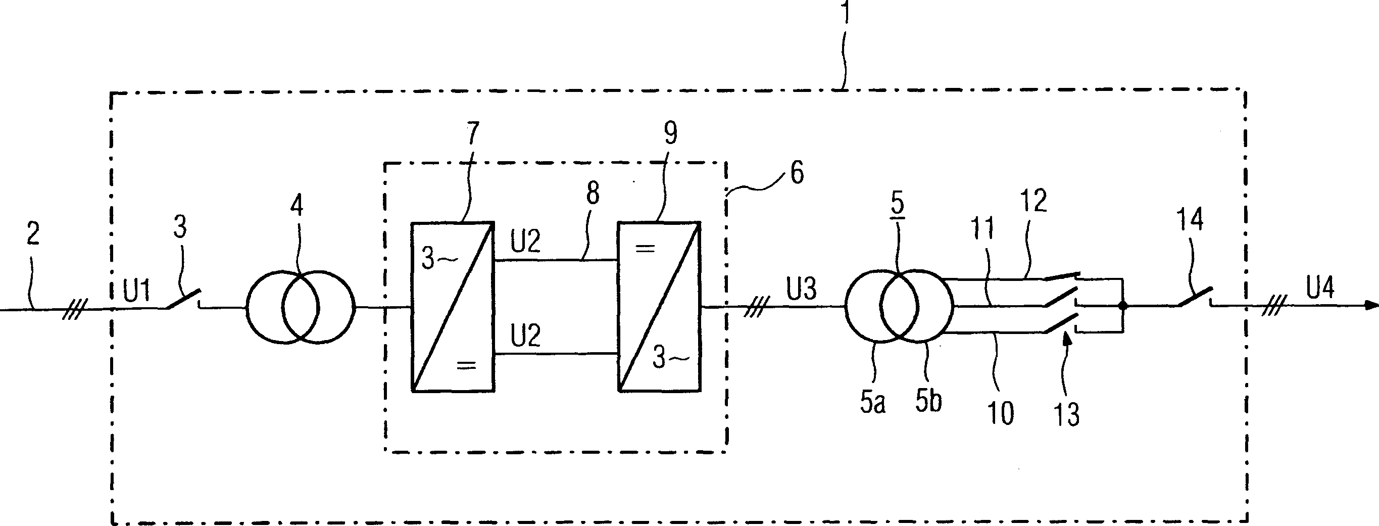
[0011] The drive belongs to a magnetic levitation train (not shown) that moves along the running track and consists of a linear electric motor whose stator extends along the running track and is subdivided into stator segments. The individual stator segments can be connected temporally sequentially to the three-phase output AC voltage U4 of the output transformer 5 (primary winding 5 a, secondary winding 5 b). The output AC voltage U4 is provided by the conversion unit 1, and the three-phase power grid 2 with a medium voltage level supplies power for the conversion unit.

[0012] The conversion unit 1 comprises an input switch 3 connected to the supply network 2 (voltage U1 ), which is connected upstream of an input transformer 4 . Between the input transformer 4 and the output transformer 5 is a converter 6 .

[0013] The converter 6 consists of a rectifier 7 for generating an intermediate circuit DC voltage U2, an intermediate circuit 8 and an inverter 9, wherein the invert...


PUM


Abstract

A drive system for a vehicle moving along a trackway, particularly a magnetic levitation train, includes a linear motor which has a stator extending along the trackway, and can be connected to a three-phase output voltage of an output transformer. An electrical power supply supplies a three-phase supply voltage which is converted into a three-phase alternating voltage of predeterminable frequency and amplitude by a converter unit. The alternating voltage being connected to the primary winding of an output transformer. To provide for more differentiated power adaptation it is proposed that the secondary winding of the common output transformer be provided with taps which, in transformer mode, can be connected and disconnected by a stepping switch for adjusting and correcting the desired output voltage.

Description

technical field [0001] The invention relates to the drive of vehicles moving along a running track, in particular a maglev train. Background technique [0002] The drive of maglev trains is known. Maglev trains have a linear motor with a stator that extends along the track. The stator is subdivided into stator segments which can be connected synchronously with the movement of the maglev train along the running track to an output transformer providing a three-phase output AC voltage. In order to generate the three-phase output AC voltage, the three-phase grid AC power of the network is rectified in a converter, and the intermediate circuit voltage thus formed is converted into a three-phase AC voltage by an inverter corresponding to a predetermined frequency. These two AC voltages are applied to the primary winding of the output transformer. In this way, during the operation of the transformer, the secondary winding of the output transformer provides the three-phase AC vol...

Claims


Application Information

Patent Timeline
IPC IPC(8): B60L13/03
CPCB60L13/03H01F29/02H01F30/12H02P13/06H02P25/18B60L2200/26
Inventor 马库斯·恩格尔赖纳·迈耶沃尔特·赛科特
Owner SIEMENS AG
Why Eureka
Try Eureka